Intent: demonstrate — this guide walks school IT coordinators, network administrators, and facilities teams through a school recognition display VLAN tagging test to confirm that a hall-of-fame kiosk, donor wall screen, or athletic record board is correctly isolated on its assigned VLAN and reliably reaches the cloud content management system (CMS) that keeps the display current without exposing the device to student or guest network segments.
School networks commonly divide traffic into multiple VLANs — separate virtual segments for student devices, staff workstations, administrative systems, guest Wi-Fi, and building automation. A recognition display is a fixed, unattended device with a predictable traffic pattern: it needs outbound HTTPS access to the CMS platform that manages athlete profiles, award records, and seasonal content, and it needs to receive incoming management traffic from the IT team. When the switch port serving the display is assigned to the wrong VLAN — or when the VLAN is correctly assigned but inter-VLAN routing rules block the CMS destination — the display loses content updates silently. The hall-of-fame kiosk in the lobby continues showing whatever content was cached locally, but new athlete recognitions, updated award records, and time-sensitive program announcements never reach the screen. Running a structured VLAN tagging test before the display is declared production-ready catches these failures at commissioning, before the athletic director or alumni coordinator discovers them.
The quick answer: confirm the switch port is configured as an access port on the correct VLAN ID, verify the display receives a DHCP address in the expected subnet, confirm outbound HTTPS to the CMS platform succeeds, and check that a test packet from outside the recognition VLAN cannot reach the display’s management interface. If any check fails, the port VLAN assignment, the inter-VLAN routing ACL, or the firewall policy needs correction before the display enters unattended operation.
This procedure applies to recognition displays connected by Ethernet — including wall-mounted hall-of-fame kiosks, freestanding donor wall screens, and athletic record boards served by a dedicated media PC or embedded player. The test sequence is identical for a 55-inch lobby installation and an 86-inch corridor recognition wall as long as both connect to the school’s managed switch infrastructure.

A recognition display that cannot reach its cloud CMS will cache-serve stale content silently — VLAN tagging validation catches this failure before the program goes live
Why VLAN Segmentation Matters for Recognition Displays
A recognition kiosk in a school lobby is unlike any other device on the school network. It operates unattended throughout the school day, connects to a cloud platform that holds personally identifiable information about student athletes and award recipients, and displays content visible to visitors, parents, and community members. Those characteristics create three reasons to place the display on a dedicated VLAN rather than on the general staff or student network.
Isolation limits exposure. A display device in a publicly accessible hallway has a fixed physical location and no active user session during most operating hours. Placing it on a dedicated display VLAN means that if the device is ever targeted by a network-level attack — port scanning, unauthorized management attempts — the blast radius is limited to the display segment rather than reaching staff workstations or administrative systems. Schools that run athletic and academic recognition programs alongside sensitive student records benefit from the defense-in-depth that VLAN isolation provides.
Predictable traffic simplifies firewall rules. Recognition display traffic is narrow and consistent: outbound HTTPS to the CMS platform, outbound NTP for clock synchronization, and inbound SSH or RDP from the IT management subnet. Placing the display on its own VLAN makes it straightforward to write a minimal allowlist firewall policy that permits only those flows and denies everything else. Attempting to write the same policy for a device on the general staff VLAN requires carving out exceptions in a much larger, more complex ruleset.
Content delivery stays reliable under load. School networks frequently experience high utilization during peak hours — morning device check-ins, streaming video in classrooms, large file transfers during the school day. A display VLAN with a defined bandwidth reservation or quality-of-service (QoS) policy ensures that CMS content synchronization — athlete photos, highlight videos, updated award records — is not starved behind bulk student traffic. For programs that publish new recognitions on a tight schedule around award ceremonies and seasonal highlights, a dedicated VLAN with reliable throughput keeps published content visible on time.
VLAN Tagging Fundamentals for School IT Teams
IEEE 802.1Q VLAN tagging is the standard mechanism that managed switches use to carry traffic from multiple virtual networks across shared physical infrastructure. Understanding the key concepts makes the test procedure easier to follow and simplifies troubleshooting when a step fails.
VLAN ID. Each VLAN is assigned a numeric identifier — the VLAN ID — in the range 1 to 4094. School networks commonly use structured numbering conventions: VLAN 10 for staff, VLAN 20 for student devices, VLAN 30 for guest Wi-Fi, and a dedicated VLAN such as VLAN 40 or VLAN 50 for building devices including recognition displays and digital signage. The VLAN ID for the recognition display should be documented in the school’s network configuration records before the display is installed.
Access ports and trunk ports. A switch port configured as an access port belongs to a single VLAN. The switch strips the 802.1Q tag from frames leaving the port toward the connected device and adds the tag to frames arriving from that device. The connected device — the recognition display media PC or embedded player — does not need to understand VLAN tagging at all. A switch port configured as a trunk port carries multiple VLANs simultaneously, each frame carrying its VLAN ID in the 802.1Q header. Trunk ports connect switches to each other and switches to routers. For a recognition display’s switch port, the correct configuration is almost always an access port on the display VLAN — not a trunk.
Native VLAN. On a trunk port, the native VLAN carries untagged frames. Misconfiguring a display’s access port as a trunk port with an unintended native VLAN can silently place the display in the wrong network segment — a common commissioning mistake that causes CMS connectivity failures without producing an obvious error.
Inter-VLAN routing. Traffic between VLANs passes through a Layer 3 device — typically the school’s core switch or router — subject to access control lists (ACLs) or firewall policy. A recognition display on VLAN 40 reaching a CMS hosted on the internet passes through the inter-VLAN routing point to the school’s internet uplink. If that ACL blocks HTTPS traffic from VLAN 40, the display cannot synchronize content even though its VLAN assignment is correct.
Tools Required
| Tool | Use | Notes |
|---|---|---|
| Managed switch CLI or web interface | Verify port VLAN assignment, confirm access vs. trunk mode, check allowed VLAN list | Requires read-only or administrator access to the switch; CLI commands vary by vendor (Cisco IOS, Aruba OS, Juniper EX, etc.) |
| DHCP server logs or lease table | Confirm the display received a DHCP address in the expected subnet for the display VLAN | Access through the school's DNS/DHCP management console or router lease table; a display IP outside the expected range indicates VLAN misconfiguration |
| Network analyzer or ping utility on the display | Test outbound HTTPS connectivity to the CMS platform; confirm DNS resolution; check default gateway reachability | Use the display media PC's Command Prompt or PowerShell; curl, ping, and nslookup are sufficient; no additional software required |
| Laptop or workstation on a separate VLAN | Verify that the display's management interface is not reachable from outside the display VLAN | Isolation test; connect the test device to the student or guest VLAN and attempt to ping the display's IP address — the attempt must fail |
| School network diagram or VLAN documentation | Reference document for expected VLAN ID, subnet range, default gateway, and DNS servers for the display VLAN | If documentation does not exist, create it as part of this test; it becomes the baseline for future troubleshooting |
| CMS platform administrator account | Confirm that the display appears online in the CMS dashboard after connectivity is validated | Use the school's CMS credentials; a display showing "online" in the management portal confirms end-to-end connectivity including authentication |
Pre-Test: Document the Expected Network Configuration
Before touching the switch or display, document the expected configuration so each test step has a clear pass criterion.
- Retrieve the VLAN ID assigned to recognition displays from the school’s network documentation. If no documented VLAN exists for displays, coordinate with the network administrator to assign one before proceeding.
- Note the subnet associated with that VLAN — for example, 192.168.40.0/24 for VLAN 40. The display should receive a DHCP address in this range.
- Record the default gateway IP for the display VLAN — typically the school’s core switch or router’s VLAN interface IP.
- Record the DNS server IPs the display should use — typically the school’s internal DNS or the district’s DNS resolvers.
- Identify the CMS platform’s hostname or IP that the display must reach for content synchronization. This is the primary outbound connectivity target.
- Note the switch model and port number where the display’s Ethernet cable terminates. Physical labeling of the cable and switch port during installation prevents ambiguity during the test.
Record all six values in a commissioning document before beginning Step 1.
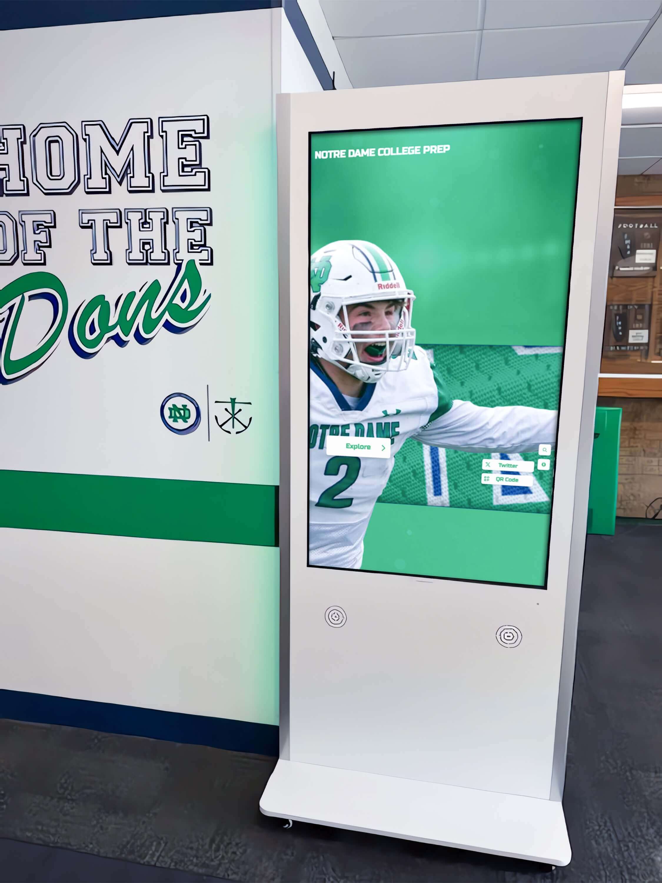
Documenting the expected VLAN ID, subnet, and CMS hostname before beginning the test gives each step a clear pass criterion and speeds up troubleshooting if any check fails
School Recognition Display VLAN Tagging Test Checklist
Step 1: Verify Switch Port VLAN Assignment
Confirm that the physical switch port serving the recognition display is configured as an access port on the correct VLAN ID.
- Log in to the managed switch’s CLI or web management interface with an administrator account.
- Identify the port number that the display’s Ethernet cable connects to. On most managed switches, port labels correspond to the physical jack numbers on the switch panel.
- Run the appropriate vendor command to show the port’s VLAN configuration:
- Cisco IOS / IOS-XE:
show interfaces GigabitEthernetX/X switchport - Aruba / HPE ProCurve:
show interfaces X detail - Juniper EX:
show ethernet-switching interface ge-0/0/X - Ubiquiti UniFi: view the port profile in the UniFi Network controller under Switch → Ports
- Cisco IOS / IOS-XE:
- In the output, confirm two things: the administrative mode is access (not trunk or dynamic), and the access VLAN matches the documented display VLAN ID.
- If the port shows trunk mode, or if the access VLAN does not match, reconfigure the port:
- Cisco IOS example:
interface GigabitEthernetX/X→switchport mode access→switchport access vlan <VLAN_ID> - Apply the equivalent command for your switch vendor
- Cisco IOS example:
- After any reconfiguration, re-run the show command to confirm the change took effect.
Record the port mode and VLAN ID from the switch output.
Pass criteria: Port administrative mode = access; access VLAN = documented display VLAN ID.
Step 2: Verify the Display Receives a DHCP Address in the Correct Subnet
After confirming the switch port VLAN assignment, validate that the display received an IP address in the expected subnet for that VLAN.
- On the display’s media PC or embedded player, open a Command Prompt or PowerShell window and run
ipconfig /all(Windows) orip addr show(Linux/embedded OS). - In the output, locate the Ethernet adapter connected to the school network. Confirm the IPv4 address falls within the documented subnet for the display VLAN — for example, 192.168.40.x for VLAN 40 with subnet 192.168.40.0/24.
- Confirm the Default Gateway matches the VLAN gateway IP documented in the pre-test step.
- Confirm the DNS Servers match the documented DNS server IPs.
- If the display received an address in the wrong subnet — or a 169.254.x.x self-assigned address indicating DHCP failure — check the switch port VLAN assignment from Step 1, verify the DHCP scope for the display VLAN includes available leases, and confirm the DHCP server or DHCP relay is configured to serve the display VLAN.
- From the DHCP server or router, check the lease table to confirm the display’s MAC address is listed with an address in the correct subnet. This cross-check confirms the DHCP server correctly routed the request based on the VLAN.
Document the display’s assigned IP, subnet mask, gateway, and DNS server IPs.
Pass criteria: Display IP in documented display VLAN subnet; gateway and DNS match documented values; DHCP lease visible in server lease table.
Step 3: Test Default Gateway and DNS Reachability
Before testing outbound CMS connectivity, confirm that the display can reach its default gateway and resolve DNS names. These are prerequisites for any internet-bound traffic.
- From the display’s Command Prompt or PowerShell, ping the default gateway:
ping <gateway_IP>. A successful ping confirms Layer 3 connectivity within the display VLAN. - If the gateway ping fails, check whether the inter-VLAN routing interface for the display VLAN is configured on the core switch or router. The VLAN interface (SVI on Cisco, routed VLAN interface on Aruba) must be up and assigned the gateway IP.
- Test DNS resolution:
nslookup <CMS_hostname>orResolve-DnsName <CMS_hostname>in PowerShell. A successful DNS response with a public IP confirms the display can resolve the CMS platform’s address. - If DNS resolution fails, check whether the display VLAN’s DNS server IPs are reachable from the display (ping each DNS server IP) and whether the ACL on the inter-VLAN routing point allows DNS traffic (UDP port 53) from the display VLAN to the DNS server subnet.
- Test NTP reachability if the display uses a network time source:
Test-NetConnection <ntp_server_IP> -Port 123in PowerShell. Accurate time is required for CMS authentication and content scheduling on recognition displays that show dated program records and time-bound recognition announcements.
Pass criteria: Gateway ping succeeds; DNS resolves CMS hostname to a public IP; NTP server reachable if applicable.
Step 4: Test Outbound HTTPS Connectivity to the CMS Platform
Confirm that the display can establish an HTTPS connection to the cloud CMS platform that manages the recognition content.
- From the display’s Command Prompt or PowerShell, test the HTTPS connection using one of the following:
- PowerShell:
Test-NetConnection <CMS_hostname> -Port 443 - Command Prompt (curl if available):
curl -v https://<CMS_hostname>
- PowerShell:
- A successful result shows TcpTestSucceeded: True (PowerShell) or an HTTP response code (curl). This confirms the TCP handshake completed — the firewall and ACL are permitting the connection.
- If the connection fails, check the inter-VLAN routing ACL and any perimeter firewall rules that apply to traffic originating from the display VLAN destined for external HTTPS. The firewall policy should explicitly permit outbound TCP 443 from the display VLAN to any destination (or to the CMS platform’s IP range if a more restrictive allowlist is in place).
- If the school uses a web proxy for outbound HTTPS, confirm the display is configured to use the proxy or is on the proxy bypass list. Recognition display media players often do not use system-level proxy settings automatically — the CMS client application may need explicit proxy configuration.
- Log in to the CMS platform’s management portal with the school’s administrator account and confirm the display appears as online or connected. A display that passes the TCP connection test but shows offline in the CMS indicates an authentication issue rather than a VLAN or firewall issue — check the device registration token and CMS account credentials.
Pass criteria: TcpTestSucceeded = True on port 443 to CMS hostname; display appears online in the CMS management portal.
Step 5: Verify Isolation — Confirm the Display Is Unreachable from Other VLANs
Confirming that the display VLAN is properly isolated prevents unauthorized access from student or guest network segments. This step validates the ACL or firewall rules that restrict inter-VLAN traffic to the display.
- Connect a test laptop or workstation to the student VLAN — either via a student network Wi-Fi SSID or by plugging into a student-VLAN switch port. Confirm the test device receives an address in the student VLAN subnet.
- From the test device, attempt to ping the recognition display’s IP address:
ping <display_IP>. The ping should time out — no response. - From the test device, attempt to connect to the display’s management port:
Test-NetConnection <display_IP> -Port 22(SSH) orTest-NetConnection <display_IP> -Port 3389(RDP). Both should report TcpTestSucceeded: False. - If any inter-VLAN ping or connection attempt succeeds, the ACL between the student VLAN and the display VLAN is not configured correctly. The inter-VLAN routing ACL should deny all traffic from the student VLAN to the display VLAN subnet, while permitting the specific flows needed for IT management from the staff or IT VLAN.
- Repeat the ping test from the guest Wi-Fi VLAN if one is present. Guest VLAN isolation is especially important for displays installed in common areas where community visitors, parents attending events, and alumni returning for recognition ceremonies and hall-of-fame programs can join the guest network.
Document the inter-VLAN isolation result for each tested source VLAN.
Pass criteria: Display IP unreachable (ping timeout, TCP connection refused or timeout) from student VLAN and guest VLAN.
Step 6: Verify IT Management Access from the Authorized Subnet
Confirm that IT staff can reach the display’s management interface from the authorized management VLAN or subnet, confirming the ACL permits the correct flows while blocking all others.
- From a workstation on the IT management VLAN or staff network, attempt to ping the display IP. The ping should succeed.
- If the display supports remote management — SSH for embedded Linux players, RDP for Windows media PCs — test the connection:
Test-NetConnection <display_IP> -Port 3389(RDP) orTest-NetConnection <display_IP> -Port 22(SSH). The connection should succeed. - Optionally, open a remote desktop session to the display media PC and confirm the content platform is running normally. This also validates that the display’s CMS connection remains active during remote access — some kiosk platforms pause CMS sync during an active remote session.
- If IT management access fails but the display is correctly isolated from student and guest VLANs, review the ACL entries on the inter-VLAN routing point. A deny-all policy applied after limited permit rules may be blocking the management subnet — confirm the permit rule for IT management traffic appears before the deny rule in the ACL.
- Document the authorized management source VLAN and the result of the remote access test. Schools that manage hall-of-fame program content and display operations remotely rely on this access path for content updates, software maintenance, and troubleshooting — confirming it works during commissioning prevents outages during the school year.
Pass criteria: Ping succeeds from IT management VLAN; remote management connection (RDP/SSH) succeeds from IT management workstation.
Step 7: Record Results and Make a Go / No-Go Decision
Document the full VLAN tagging test before releasing the display to unattended operation.
| Test Item | Expected Result | Actual Result | Pass / Fail | Tested By | Date |
|---|---|---|---|---|---|
| Switch port mode | Access mode on display VLAN ID | ||||
| Display IP address | Address in display VLAN subnet | ||||
| Default gateway reachability | Ping succeeds to gateway IP | ||||
| DNS resolution | CMS hostname resolves to public IP | ||||
| HTTPS connectivity — port 443 | TcpTestSucceeded = True to CMS host | ||||
| CMS portal status | Display shows online in CMS dashboard | ||||
| Isolation — student VLAN | Display IP unreachable from student VLAN | ||||
| Isolation — guest VLAN | Display IP unreachable from guest VLAN | ||||
| IT management access | RDP or SSH succeeds from IT management subnet |
Go / No-Go rule: All nine items must show a passing result before the display enters unattended operation. A display that passes connectivity checks but fails isolation checks should not be placed in a publicly accessible location until the ACL is corrected — an improperly isolated display on a shared school network creates unnecessary exposure for the recognition program’s connected cloud platform.
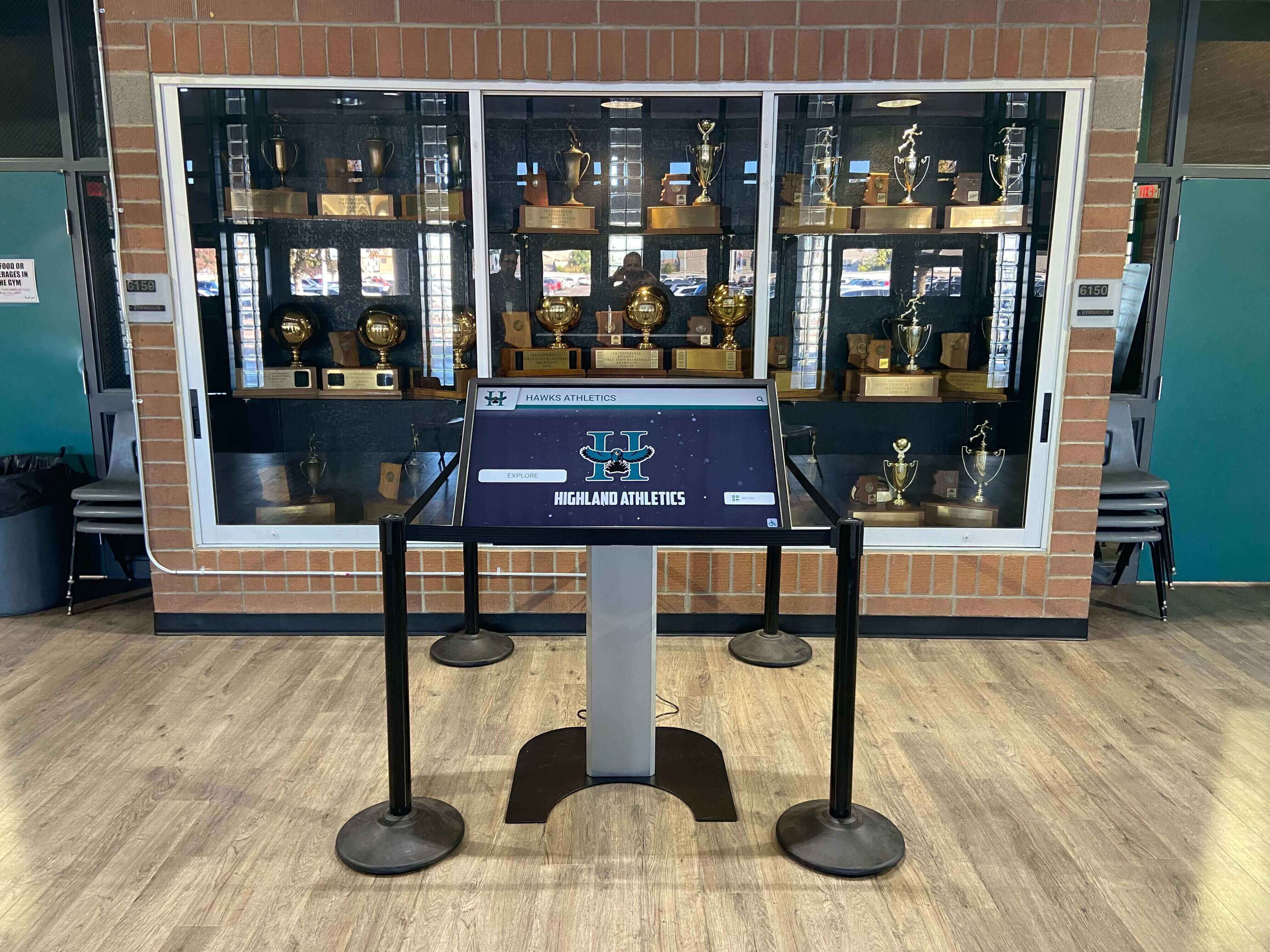
A completed VLAN tagging test record gives the next IT coordinator a documented network baseline and speeds up troubleshooting if content synchronization fails after a network change
Troubleshooting: Common VLAN Configuration Failures
| Symptom | Probable Cause | Resolution |
|---|---|---|
| Display gets a 169.254.x.x self-assigned IP | DHCP request not reaching the DHCP server — VLAN not trunked to the distribution switch where the DHCP server or DHCP relay is configured | Confirm the display VLAN is in the allowed VLAN list on all trunk links between the access switch and the distribution/core switch; verify the DHCP relay (ip helper-address) is configured on the VLAN interface at the Layer 3 switch |
| Display gets an IP in the wrong subnet (e.g., staff VLAN range) | Access port assigned to the wrong VLAN ID; port is on the staff VLAN instead of the display VLAN | Reconfigure the access port with the correct display VLAN ID; release and renew the DHCP lease on the display after the switch change |
| Gateway ping succeeds but HTTPS to CMS fails | Firewall or ACL blocks outbound HTTPS from the display VLAN; web proxy required but not configured | Review the perimeter firewall policy and inter-VLAN ACL for rules that deny TCP 443 from the display VLAN subnet; configure proxy settings in the CMS client application if the school routes outbound HTTPS through a proxy |
| CMS hostname resolves but TcpTestSucceeded = False on port 443 | Content filtering or firewall policy blocks the specific CMS domain; SSL inspection is interrupting the handshake | Add the CMS platform's domain to the firewall or content filter allowlist; if SSL inspection is in use, add the CMS domain to the inspection bypass list to prevent certificate validation errors |
| Display appears offline in CMS portal despite successful TCP connection test | Device registration token expired or incorrect; CMS account credentials not stored on the display; CMS client application not running | Re-register the display in the CMS portal; verify the CMS client application is in the startup items list on the media PC; check the application log for authentication error messages |
| Display reachable from student VLAN (isolation test fails) | ACL between student VLAN and display VLAN is missing or incomplete; inter-VLAN routing is permit-all by default | Add an explicit deny rule in the inter-VLAN ACL blocking all traffic from the student VLAN subnet to the display VLAN subnet; apply the ACL in the inbound direction on the student VLAN interface at the Layer 3 switch |
| IT management access fails even though the display is on the network | Deny rule in the ACL appears before the permit rule for the IT management subnet; RDP or SSH disabled on the display media PC | Review ACL entry order — permit rules for the IT management subnet must precede the deny rule for all other sources; confirm RDP is enabled in Windows Settings → Remote Desktop on the display media PC |
| VLAN configuration correct but display loses CMS connection after a network change | Network change modified the inter-VLAN ACL, the DHCP scope, or the uplink trunk VLAN list without updating the display VLAN | Re-run Steps 3–5 after any network change that touches the distribution or core switches; include display VLAN in the change review checklist for future network modifications |
Post-Test Steps Before Returning to Unattended Operation
After all test items pass, complete these steps before closing out the commissioning session.
Export and save the switch port configuration. Run the switch show command for the display port and save the output to the school’s IT documentation folder alongside the display’s serial number and physical location. If a future network change resets the port to default VLAN or changes the access VLAN, this record provides the correct baseline to restore.
Document the firewall and ACL rules. Record the specific ACL entries that permit CMS HTTPS traffic from the display VLAN and deny inter-VLAN access from student and guest segments. Schools that maintain detailed digital hall-of-fame content records and annual recognition archives benefit from the same structured documentation discipline applied to the network configuration that runs those programs.
Label the switch port. Apply a physical label or add a port description in the switch configuration identifying the port as the recognition display connection. Port descriptions in the switch config — added via
description Recognition-Display-Lobbyor equivalent — survive firmware updates and appear in SNMP monitoring output, making future identification faster.Register the display in the school’s asset management system. Record the display’s MAC address, assigned IP, VLAN ID, switch name, and port number in the IT asset management or network documentation system. If the DHCP lease is assigned dynamically, consider creating a static DHCP reservation for the display MAC address so the IP remains consistent across reboots and lease renewals — this keeps firewall logs and CMS records correlated to a stable address.
Schedule a follow-up check at 30 days. After any significant network change — switch firmware update, VLAN renumbering, firewall policy refresh — re-run Steps 3 through 5 to confirm the display’s connectivity and isolation are still intact. Add this check to the recognition display’s maintenance schedule alongside content audits and hardware inspections. Programs that use the display for ongoing alumni recognition and community engagement depend on reliable CMS connectivity throughout the school year, not just at commissioning.
VLAN Tagging for Multi-Display Installations
Schools running recognition displays in multiple locations — an athletics corridor, a main lobby donor wall, and a college and career resource center interactive display — should place all recognition displays on the same display VLAN unless there is a specific reason to segment them differently. A single display VLAN simplifies DHCP scope management, produces a single consistent firewall policy, and makes the test procedure uniform across all installations.
For multi-display deployments, run Steps 1 through 6 on each display independently. Do not assume that a passing result on one display means all others share the correct configuration — switch ports on different access switches may be configured differently, and VLAN trunk links may carry the display VLAN on some uplinks but not others.
Additional considerations for multi-display schools:
- Verify the display VLAN is in the allowed VLAN list on every trunk link in the path from each access switch to the core routing layer. A missing VLAN on one trunk segment is a common cause of DHCP failure on displays connected to secondary access switches.
- Use consistent port descriptions across all display switch ports so that network monitoring tools can identify display devices without referencing the asset documentation separately.
- If the school’s network management system (NMS) or SNMP monitoring platform is in use, add the display VLAN’s subnet to the monitoring scope so that a display going offline produces an alert rather than being discovered manually.
- Include the display VLAN test in the acceptance criteria for any future switch replacement, network segment redesign, or school expansion. A new access switch serving a new hallway where a recognition display is installed should be tested with this checklist before the display is declared production-ready.
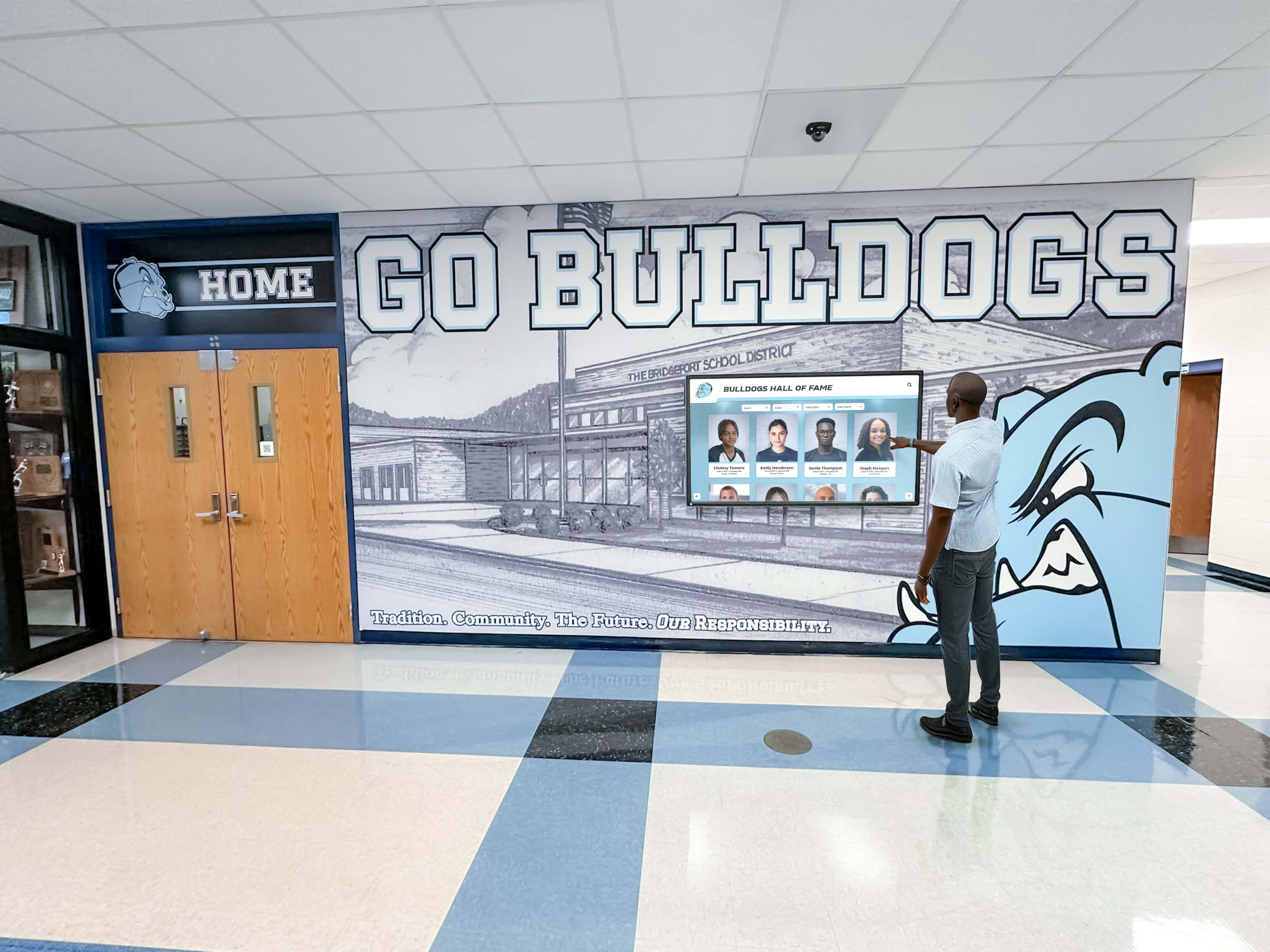
Multi-display schools should run the full VLAN tagging test on each display port independently — a passing result on one access switch does not guarantee identical configuration on adjacent switches
How VLAN Validation Fits a Broader Network Reliability Program
A passing VLAN tagging test confirms the display’s network configuration is correct at commissioning. Maintaining that reliability through the school year requires a few additional practices.
Change management awareness. Scheduled network changes — firmware updates, policy refreshes, VLAN renumbering — that are not reviewed against the display VLAN documentation are the most common cause of post-commissioning connectivity failures. Adding recognition display connectivity to the change impact review checklist for any modification that touches the display VLAN, its ACL, or the uplink trunk configuration costs little time and prevents the athletic director from discovering a content outage the week before an awards program.
Monitoring. A recognition display that loses CMS connectivity does not produce a visible error for visitors — it simply continues showing whatever content was last synchronized. If the school’s network monitoring platform supports SNMP or ICMP monitoring, adding the display IP to a monitored asset group enables proactive alerts when the device goes offline, rather than waiting for a staff member to notice stale content.
Firmware and driver currency. Network interface drivers on the display media PC interact with the switch’s auto-negotiation and VLAN tagging stack. Outdated NIC drivers occasionally cause VLAN tagging anomalies — frames arriving without the expected 802.1Q tag, or VLAN ID mismatches at the driver level. Keeping the media PC’s NIC driver current as part of routine OS patching prevents this class of failure. Similarly, switch firmware updates occasionally modify default port behavior — reviewing the switch vendor’s release notes when applying firmware updates prevents unexpected changes to access port VLAN assignments.
Content platform integration testing after network changes. After any network modification, log in to the CMS management portal and confirm all displays in the building show online status. Running a manual content push from the CMS to each display after a network change confirms that connectivity is fully functional at the application layer, not just at the TCP layer.
Frequently Asked Questions
What VLAN ID should a school use for recognition displays?
The specific VLAN ID does not matter as long as it is consistently assigned and documented. Many school districts use a structured numbering convention — for example, VLAN 10–30 for user device categories and VLAN 40 or higher for building systems and digital signage. What matters is that the chosen VLAN ID is not already in use for another purpose, that it has a dedicated DHCP scope, and that the firewall and ACL rules are written specifically for that VLAN. If the school already uses a digital signage VLAN for other displays, placing recognition displays on the same VLAN is reasonable as long as the traffic and management requirements are compatible.
Can a recognition display use Wi-Fi instead of Ethernet for the VLAN tagging test to apply?
VLAN segmentation applies to both wired and wireless connections. On a wireless network, the equivalent of VLAN tagging is the SSID-to-VLAN mapping: a dedicated display Wi-Fi SSID that maps to the display VLAN. If a recognition display connects over Wi-Fi, the test procedure steps for connectivity (Steps 3–4) and isolation (Step 5) apply without change — only Step 1 is replaced by verifying the SSID-to-VLAN mapping in the wireless controller rather than the switch port configuration. A wired Ethernet connection is generally preferred for recognition display media PCs because it eliminates wireless signal variability and simplifies the VLAN configuration to a single switch port setting.
What if the school’s network does not use VLANs at all?
Schools running a flat network with a single IP subnet for all devices can still isolate recognition displays using firewall rules applied at the perimeter or a managed switch ACL applied per port. The isolation goal is the same — restrict lateral access to the display’s management interface and limit the display’s outbound traffic to the CMS platform — but the mechanism is port-level ACLs rather than VLAN segmentation. The connectivity and isolation test steps from this guide still apply; only the switch configuration step changes.
How do we handle the VLAN configuration if the recognition display media PC is replaced?
Replacing the media PC does not change the switch port VLAN assignment — the VLAN is a property of the port, not the device. Connect the replacement PC to the same switch port and verify it receives a DHCP address in the display VLAN subnet. If the replacement PC has a different MAC address and a static DHCP reservation was configured for the original PC, update the reservation with the new MAC address. Re-run Steps 3 and 4 to confirm connectivity after the hardware swap.
Why does our recognition display show stale content even though the network appears to be working?
A display showing outdated content despite passing the basic ping and DNS tests typically indicates an issue at the application layer rather than the network layer. Check the CMS portal to confirm the display appears online — not just reachable. Common application-layer causes include: the CMS client application is running but an authentication token has expired; the display’s clock is out of sync with the NTP server, causing certificate validation failures; or the CMS platform’s IP range changed and the firewall allowlist was not updated. Run Step 4 of the test procedure to confirm the HTTPS connection to the CMS hostname is active, then log in to the CMS portal and check whether the display shows a synchronization timestamp consistent with the most recent content update.
Does the VLAN tagging test need to be repeated after every school year?
The switch port VLAN assignment does not change on its own, but the policies that govern what the VLAN can reach do change — through firewall updates, content filter policy refreshes, and ACL modifications made for unrelated network changes. Running a brief connectivity verification at the start of each school year — gateway ping, DNS resolution, HTTPS to CMS, and CMS portal status check — takes under ten minutes per display and confirms that summer network maintenance did not inadvertently break the recognition display’s connectivity. Schools that publish new athlete recognitions and award program records at the start of each school year benefit from a verified connection before the first recognition event of the fall season.
A school recognition display VLAN tagging test adds under an hour to commissioning and permanently documents the network configuration that keeps the hall-of-fame kiosk, donor wall, and athletic record board running throughout the school year. Verify the switch port, confirm the DHCP address, test CMS connectivity, validate isolation from student and guest segments, and confirm IT management access before releasing the display to unattended operation. Document every setting and store the test record alongside the display’s asset information — this baseline saves significant diagnostic time the next time a network change touches the display VLAN.
Looking for a recognition display partner that manages the complete network setup, cloud CMS configuration, and ongoing reliability for your school’s hall of fame or athletic record board? Rocket Alumni Solutions handles the full installation and configuration process, including network requirements and remote management setup, so your recognition display operates correctly from day one without requiring repeated IT intervention. Request a demo to learn how their managed approach keeps your recognition program running reliably throughout the school year.