Intent: demonstrate — this checklist walks school IT coordinators, AV teams, and facilities staff through a recognition display USB-C Alt Mode test so video output, power delivery, and touchscreen input all negotiate correctly over a single cable before a hall-of-fame wall, donor screen, or athletic record board goes live.
USB-C with DisplayPort Alt Mode (commonly called DP Alt Mode) allows a single cable to carry video signal, USB data for touch, and power simultaneously. When it works, the result is a clean single-cable installation with no separate HDMI run, no separate USB touch cable, and no separate power brick on the display. When it does not work — because the cable lacks the correct specification, the source device does not support Alt Mode on the connected port, or the display input is not configured for Alt Mode — the display either shows no image, registers no touch input, or draws insufficient power, and diagnosing which layer failed consumes time that should have been spent on content configuration. Running a structured Alt Mode test before the display is mounted and before the installer leaves costs approximately 45 to 60 minutes and eliminates the most common source of single-cable installation failures on school recognition projects.
The quick answer: connect the USB-C cable between the source device and the display, then verify three things independently — video output (check the display’s on-screen menu for active resolution and refresh rate), touch response (tap the screen and confirm pointer movement on the source device), and power delivery (if the display draws power from the cable, confirm adequate wattage with an inline USB-C power meter). Any of the three that fails points to a specific layer in the cable or configuration chain that must be resolved before the recognition display is mounted.
This procedure applies to recognition displays driven by USB-C with DisplayPort Alt Mode, including wall-mounted hall-of-fame kiosks, donor wall screens, and athletic record boards. It is hardware-neutral — the test sequence is the same for 55-inch lobby installations and 86-inch hallway recognition walls.

A single USB-C cable carrying video, touch, and power simplifies wiring — but requires a structured test before mounting to confirm all three functions negotiate correctly
Why USB-C Alt Mode Testing Matters for Recognition Displays
A recognition display in a school lobby or athletic hallway must work reliably the first time visitors see it. Unlike a back-office monitor that an IT coordinator can troubleshoot in an empty room, a hall-of-fame wall or donor recognition screen serves a public audience — parents on orientation night, recruits during campus tours, donors at dedication events, and students walking past every school day.
Single-cable USB-C installations reduce wiring complexity but create a specific failure point: if any layer of the USB-C Alt Mode negotiation fails, the entire display goes down rather than one function at a time. Three failure modes appear consistently in school recognition display installations that use USB-C:
Video fails silently. A USB-C cable without DisplayPort Alt Mode support passes power and USB data but carries no video signal. The display powers on, the source device detects the cable, but the screen shows no image — and without knowing to check Alt Mode specifically, teams may spend significant time rebooting devices and swapping source connections before identifying the cable as the root cause.
Touch input is absent. Alt Mode reconfigures the USB-C SuperSpeed lanes to carry DisplayPort video signal. USB 2.0 lanes remain available for data, including touch HID (Human Interface Device) signals from the touchscreen controller. Some cables drop USB 2.0 passthrough when operating in Alt Mode, silencing touch even when video displays correctly. This failure is particularly disruptive for recognition programs where the interactive touch experience is the primary way visitors navigate athlete profiles, award records, and program history.
Power delivery is insufficient. USB Power Delivery (USB PD) protocol allows USB-C to deliver up to 240 watts under PD Revision 3.1 — but cables, source devices, and displays must all negotiate a compatible power profile. A cable rated for 60 watts connected to a display that requires 90 watts will limit brightness, cause processing throttles, or force the display to draw from an internal reserve if one exists. Recognition displays without a separate AC connection depend entirely on USB PD for operation.
Running a structured test for each of these three functions before the display is secured to the wall identifies which layer requires attention — cable specification, source port selection, or display configuration — before it becomes a post-installation service call.
How USB-C Alt Mode Works: A Brief Primer for IT Teams
USB-C is a connector format. Alt Mode is a feature defined in the USB-C specification that allows the connector’s pins to carry non-USB protocols. DisplayPort Alt Mode uses the USB-C SuperSpeed differential pairs — normally used for USB 3.x data — to transmit DisplayPort video signal. The USB 2.0 pins remain assigned to USB 2.0 data, which carries touch HID traffic from the touchscreen overlay. USB Power Delivery runs over the VBUS and GND pins simultaneously with both video and USB data.
Three requirements must all be met for a single USB-C cable to carry video, touch, and power to a recognition display:
- The cable must support USB 3.2 Gen 1 or higher (for SuperSpeed lanes), be rated for the required USB PD wattage, and carry all Alt Mode pins without passive rewiring. A passive cable labeled “charge only” or “USB 2.0” will not pass video.
- The source device (media player, mini PC, or laptop) must have a USB-C port that explicitly supports DisplayPort Alt Mode output. Not all USB-C ports on a device support Alt Mode — some are data or charging ports only.
- The display must accept video input via USB-C (DP Alt Mode), support touch HID data over the same connection, and be configured to use the USB-C port as the active video input rather than an HDMI fallback.
When all three conditions are met, one cable delivers everything the recognition display needs. When one condition is not met, the test steps in this checklist identify which condition failed.
Tools Required
| Tool | Use | Notes |
|---|---|---|
| USB-C cable (candidate for installation) | The cable being tested | Confirm specification label: USB 3.2 Gen 1 or Gen 2, DisplayPort Alt Mode, USB PD wattage rating |
| Inline USB-C power meter | Measure actual power delivery wattage | Inline models insert between source and cable and display voltage, current, and wattage simultaneously |
| Source device (production unit) | Drive video and touch during test | Use the actual media player or mini PC being installed, not a substitute laptop |
| Display OSD (on-screen menu) | Read active resolution, refresh rate, and input source | Access via the display's control buttons or included remote; look for Signal Info or Source Info |
| Device Manager or System Information | Confirm touch HID device enumeration on the source OS | Windows: Win + X → Device Manager; macOS: System Information → USB |
| Second USB-C cable (known-good reference) | Baseline comparison if candidate cable fails | A cable verified on a prior installation eliminates variables when diagnosing failures |
| Flashlight or inspection camera | Visual check of USB-C connectors | USB-C contacts are small; bent or corroded contacts are often visible before electrical testing |
Pre-Test Visual Inspection
Complete a visual check before connecting the cable to any device. USB-C connectors fail most often where the cable jacket meets the plug housing, where repeated flexing concentrates stress.
- Inspect both USB-C connectors for bent contacts, corrosion, or cracked housing. Replace the cable if any contact is visibly deformed — bent USB-C contacts can damage the host port on the source device.
- Run a hand along the full cable length and note any hard kinks, flattened sections, or abrasion within 6 inches of either connector. Damage in this zone indicates stress at the strain relief that may produce intermittent Alt Mode failures under load.
- Read the cable’s specification label on the packaging or cable body. Confirm: USB 3.2 Gen 1 (5 Gbps) minimum for DP Alt Mode in 4-lane HBR2 configuration; USB PD rating at or above the display’s power requirement; and no “charge-only” or “USB 2.0 only” labeling.
- Confirm the source device port is documented to support DisplayPort Alt Mode output. Check the device manufacturer’s specification sheet or port markings — the DP Alt Mode symbol (a rectangular D shape with an arrow) appears next to compliant ports on many devices. A USB-C port labeled only “USB 3.x” or with a charging bolt icon may not support Alt Mode.
Replace any cable that fails the visual check or does not meet the specification requirements before continuing. A compliant replacement cable costs far less than a service call after the display is mounted.
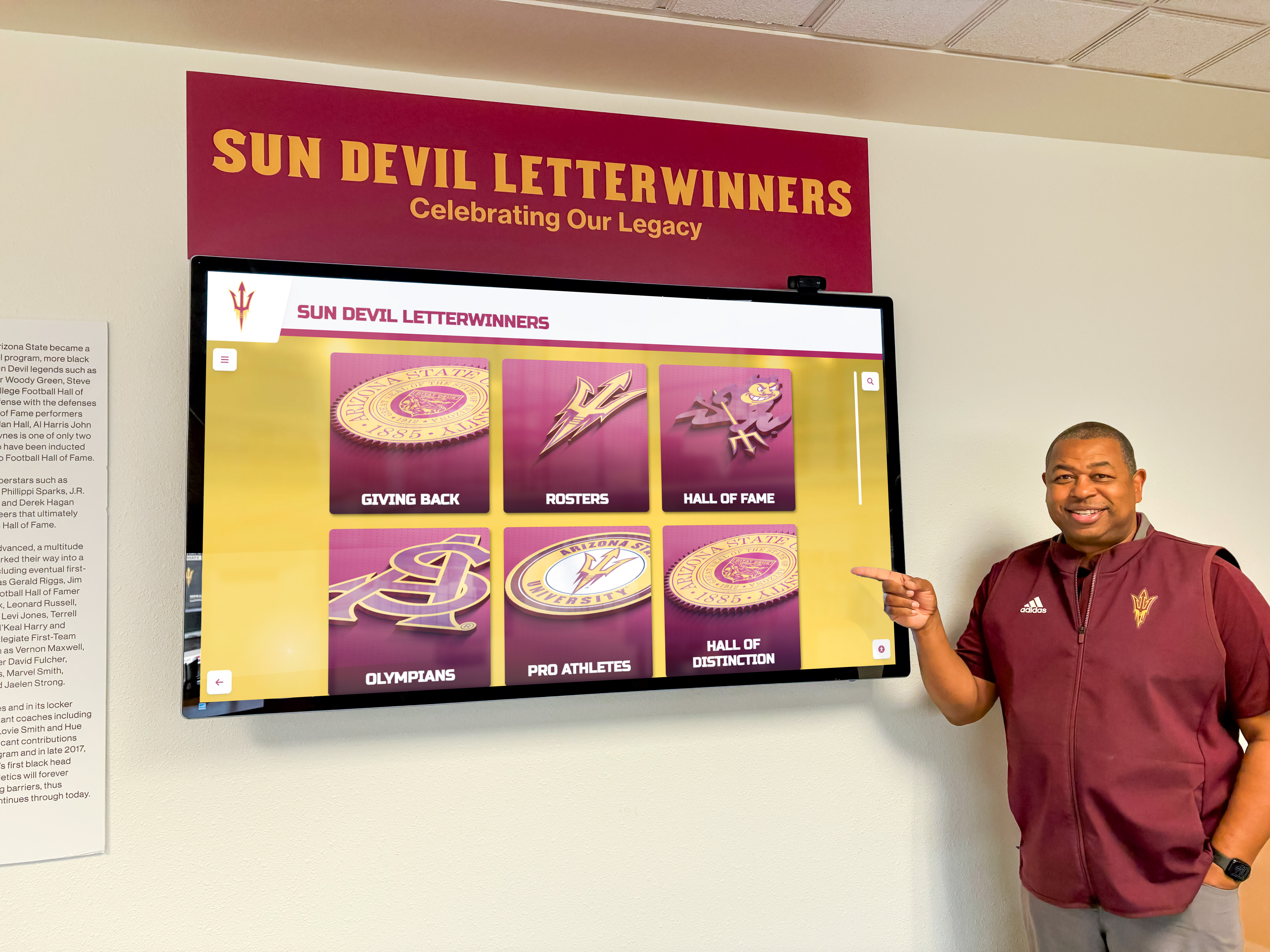
Testing the cable with the production source device — not a substitute — confirms that the actual Alt Mode negotiation works with the specific hardware being installed
Recognition Display USB-C Alt Mode Test Checklist
Step 1: Verify Cable Specification Against Installation Requirements
Collect the specification requirements for the recognition display installation before connecting anything:
- Display resolution and refresh rate: 4K (3840 × 2160) at 60 Hz requires USB-C with DP Alt Mode in 4-lane HBR3 configuration, which requires a USB 3.2 Gen 2 cable. 1080p at 60 Hz works reliably with a Gen 1 cable. Confirm the required mode matches the cable rating before proceeding.
- Power requirement: Check the display’s rated power consumption in the product datasheet. The cable’s USB PD rating must equal or exceed this figure. Most commercial 55-inch and 65-inch recognition displays draw 80–150 watts under normal brightness; verify this against the display specification, not estimates.
- Touch connection method: Confirm the display’s touchscreen controller sends its HID signal over the USB-C connection rather than a separate RS-232 or dedicated USB-A cable. If the display uses a separate touch cable alongside USB-C for video, it is not a single-cable Alt Mode setup and the touch steps in this checklist do not apply to the touch connection.
Document these three requirements in the result table at Step 6 before proceeding. Knowing the target values before the test prevents ambiguous results later.
Pass criteria: Cable specification meets or exceeds the display’s resolution, power, and touch connection requirements.
Step 2: Test Video Output (DisplayPort Alt Mode Negotiation)
Connect the USB-C cable between the source device’s Alt Mode-capable port and the display’s USB-C video input port. Power on both devices and wait 15 seconds for the Alt Mode negotiation to complete.
- Press the display’s input selector and confirm the USB-C input is shown as active — not a fallback such as HDMI-1 or VGA.
- Open the display’s OSD (on-screen display) and navigate to Signal Information, Source Info, or Picture Info.
- Confirm the reported resolution matches the installation specification (1080p or 4K as applicable).
- Confirm the refresh rate is 60 Hz — not 30 Hz. A 30 Hz reading at 4K resolution indicates the cable or port is operating at HDMI 1.4 or DP 1.1 bandwidth rather than DP 1.4, which commonly indicates a Gen 1 cable connected to a 4K/60 Hz requirement.
- Confirm the color depth in the OSD is 8-bit (24-bit RGB) minimum; 10-bit if the content management platform and display both support HDR content.
If the display shows no signal after 15 seconds, try cycling the Alt Mode re-negotiation: disconnect the cable, wait 5 seconds, and reconnect. If re-negotiation does not produce video, proceed to the troubleshooting table at Step 7 before continuing.
Pass criteria: Display reports correct resolution, 60 Hz refresh rate, and expected color depth via USB-C input.
Step 3: Test Touch Input (USB HID Over USB-C)
With video confirmed in Step 2, test touch response without disconnecting the cable.
- On the source device, open Device Manager (Windows) or System Information (macOS) and look for the display’s touchscreen controller listed under Human Interface Devices or USB devices. Its presence confirms the display’s HID descriptor reached the source OS — absence indicates the USB 2.0 data path through the cable is not functional during Alt Mode operation.
- Tap the center of the recognition display screen with a single finger. Confirm the pointer on the source device moves to match the tap location. For recognition display platforms running a dedicated kiosk application rather than a standard OS desktop, open a text input field to verify pointer response independently of the kiosk software.
- Perform a multi-touch test: touch the screen with two fingers simultaneously and confirm both points are recognized. Multi-touch is required for pinch-to-zoom on athlete archive content, category scroll gestures, and navigation interactions common in recognition program software.
- Test edge accuracy: tap each corner of the screen and confirm the registered touch point aligns within approximately 5 millimeters of the actual tap location. Edge accuracy matters for recognition displays where navigation controls, category selectors, and back buttons are placed at screen margins.
- Hold a palm flat against the screen for 3 seconds and verify the display does not register unintended inputs. Palm rejection prevents false activations when students or visitors lean against the display while reading nearby signage.
Pass criteria: HID device visible in system device list; single tap, multi-touch, and edge accuracy all pass; palm rejection active.

Multi-touch and edge accuracy tests confirm that USB HID data is passing through the Alt Mode cable alongside video — not just video alone
Step 4: Test Power Delivery (USB PD Negotiation)
This step applies only when the recognition display draws its operating power through the USB-C connection rather than a separate AC power cable. If the display has a standard IEC or NEMA AC connection and uses USB-C only for video and touch, skip to Step 5.
- Insert the inline USB-C power meter between the source device port and the cable. The meter reads the negotiated voltage, current, and wattage in real time without interrupting the Alt Mode session.
- After the display powers on and video is confirmed, read the wattage from the meter. Compare this figure against the display’s rated power consumption from the datasheet.
- If the measured wattage is below the display’s rated requirement, the USB PD negotiation has settled at a lower power profile than needed. Common causes:
- Cable is not rated for the required wattage (a cable rated for 60 W cannot deliver 100 W regardless of source capability)
- Source device USB PD output is limited to a lower wattage than the display’s request
- Display is requesting a voltage profile (such as 20 V at 5 A) that the source does not offer
- Set the display to full operating brightness — not an eco or standby mode — and observe whether the wattage reading remains stable over 3 minutes. A wattage reading that drops during sustained full-brightness operation indicates the source cannot sustain the required power profile, which may cause the display to dim, throttle its processor, or produce visible content interruptions.
Pass criteria: Measured wattage meets or exceeds the display’s rated power requirement and remains stable under sustained full-brightness operation.
Step 5: Run a 15-Minute Sustained Combination Test
After video, touch, and power delivery each pass their individual tests, run a sustained combination test before recording final results. Individual tests completed sequentially cannot detect failures that only appear when all three functions run simultaneously under load.
- Load the recognition display’s content management platform and begin playing through the standard content loop — athlete portraits, award records, program highlights, and transition sequences typical of the content that will run during athletic team recognition events and year-end award programs.
- While content plays, tap the display at 2-minute intervals and confirm touch response remains accurate throughout the 15-minute period. Some displays lose HID enumeration after 5–10 minutes if the USB 2.0 connection enters a low-power state while Alt Mode is active under sustained video load.
- Monitor the power meter reading throughout the test period. A wattage drop during sustained content playback indicates thermal throttling on the source side or a USB PD profile that reverts to a lower power tier under combined load.
- Observe video quality for any handshake resets — a brief flicker, black frame, or resolution change indicates the DisplayPort link is re-negotiating, which appears as a visible interruption at high-stakes display moments such as recognition ceremonies, reunion weekends, or alumni engagement events where families are watching the display for the first time.
- Record the sustained test start time, end time, and any anomalies observed.
Pass criteria: Touch response, video quality, and power delivery remain consistent throughout the 15-minute test without interruption, HID dropout, or power variation.
Step 6: Record Results and Make a Go / No-Go Decision
Document results before the display is mounted. A completed test record provides a baseline for future troubleshooting and becomes a permanent component of the display’s maintenance documentation — as important to long-term recognition program management as the digital platform selection decisions administrators make at the start of a recognition project.
| Test Item | Requirement | Observed Result | Pass / Fail | Tested By | Date | Action Required |
|---|---|---|---|---|---|---|
| Cable specification | USB 3.2 Gen 1+, DP Alt Mode, USB PD ≥ display rated wattage | |||||
| Video output — input source active | USB-C input selected, not HDMI or VGA fallback | |||||
| Video output — resolution | Target resolution confirmed in OSD (1080p or 4K) | |||||
| Video output — refresh rate | 60 Hz confirmed in OSD | |||||
| Touch HID enumeration | Touchscreen controller visible in system device list | |||||
| Touch accuracy — single tap | Cursor aligns with tap; ≤5 mm offset at screen edges | |||||
| Touch — multi-touch | Two simultaneous touch points both recognized | |||||
| Power delivery — wattage | Meter reading ≥ display rated power (W) | |||||
| Power delivery — stability | Wattage stable over 15-minute full-brightness test | |||||
| Sustained combination test | All functions pass for 15 minutes without interruption |
Go / No-Go rule: All ten test items must show a passing result before the display is mounted. A single failing item — particularly video negotiation or touch HID enumeration — must be resolved before mounting, not deferred. Documenting a known failure as “will address later” ensures it will not be addressed until it produces a public-facing outage.
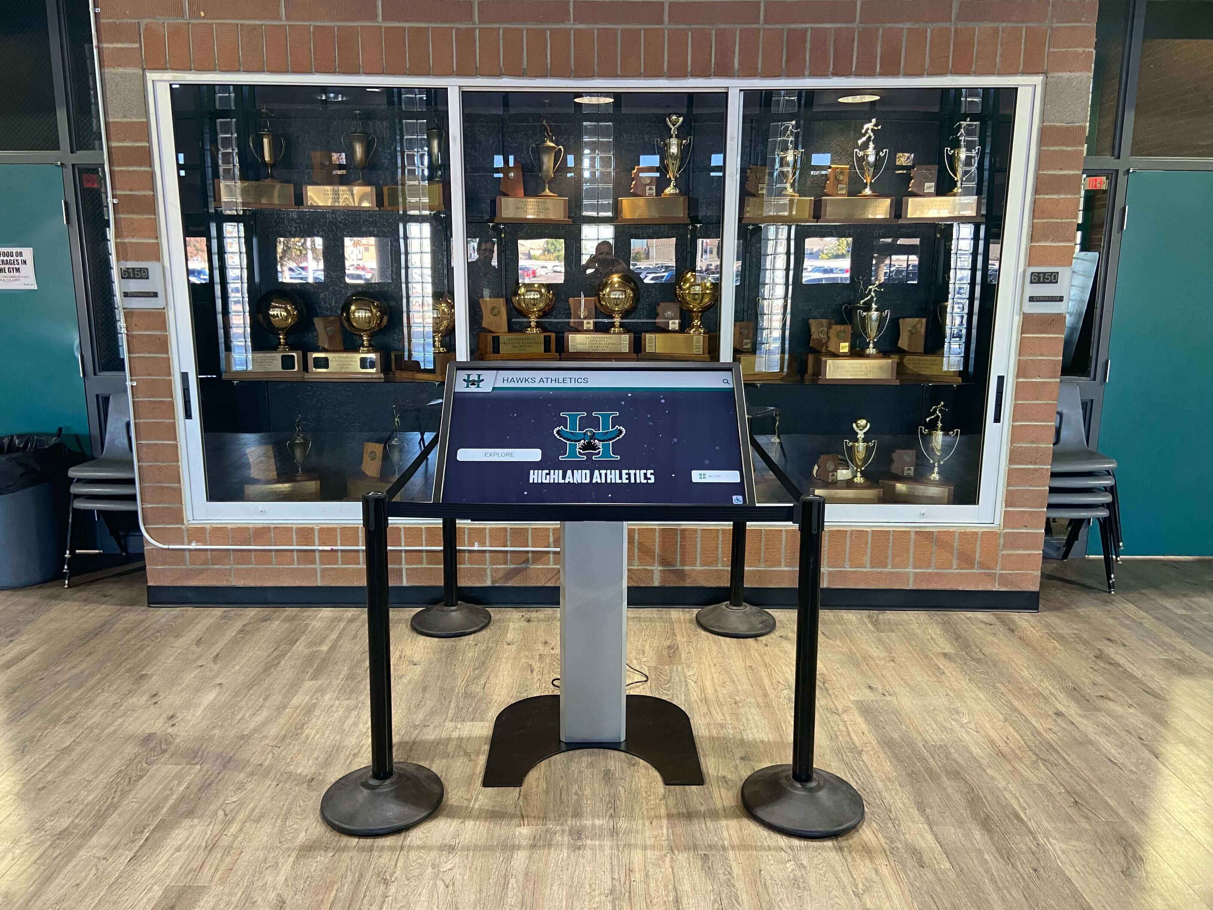
A completed Alt Mode test record documents which cable and which source port combination was verified — information that matters when the display requires service years after installation
Troubleshooting: When the Test Fails
| Failure Symptom | Probable Cause | Resolution |
|---|---|---|
| No video output after 15 seconds | Source port does not support DP Alt Mode; or cable lacks Alt Mode support | Test with known-good Alt Mode cable; confirm source port specification in device documentation; try a different USB-C port if available |
| Video output present but no touch response | USB 2.0 passthrough disabled in cable during Alt Mode; or display HID driver not installed on source OS | Replace cable with one rated for USB 2.0 passthrough in Alt Mode; install display HID driver from manufacturer |
| Correct resolution but 30 Hz instead of 60 Hz at 4K | Cable bandwidth too low (Gen 1 on a 4K/60 Hz installation); or source device limited to HBR2 output | Replace cable with USB 3.2 Gen 2; verify source device DP output mode in spec sheet |
| Power meter reads below display requirement | Cable not rated for required wattage; or source USB PD output lower than display request | Replace cable with higher USB PD rating; confirm source device USB PD output capacity |
| HID present but touch accuracy poor at screen edges | Touch calibration file missing or incorrect; or display orientation setting mismatch | Run display's built-in touch calibration procedure; confirm display orientation in OS display settings matches physical mount orientation |
| Video drops out intermittently during sustained test | Marginal cable at operating temperature; or Alt Mode re-negotiation triggered by source power management | Replace cable; disable USB selective suspend on source port in OS power settings |
| Multi-touch not recognized | Display HID descriptor reports single-touch only; or source OS HID driver limitation | Check display firmware update for multi-touch support; update source OS touch HID driver |
| Touch works initially then stops during sustained test | USB 2.0 link enters low-power state while Alt Mode active | Disable USB selective suspend for the specific port in OS power management settings; update source device USB driver |
Post-Test Steps Before Mounting
After all items pass, complete these steps before the display goes to the wall:
- Label the tested cable with the installation location, display identifier, source port used, and test date. A passed Alt Mode cable must not be swapped with an untested cable during final wall installation — cables that look identical visually may have different internal specifications.
- Photograph the source device port and cable connector at both ends, noting any identifying marks on the cable body. This record proves which hardware combination was tested if a question arises during the warranty period.
- Store the completed test record in the school’s IT documentation system alongside the display’s serial number, network port assignment, and content platform login credentials. Schools that have already completed a cable continuity check for power and Ethernet runs should file the Alt Mode test results in the same installation package.
- Verify no inline adapters exist in the final cable path between the source device and the display. Inline USB-C to HDMI or USB-C to DisplayPort adapters convert the video protocol and break the Alt Mode negotiation — the result may still produce a working display, but it is no longer a single-cable Alt Mode installation, and the touch and power test steps no longer apply as documented.
- Run a post-mount functional check after the display is secured to the wall. Cable routing around a wall mount bracket or through conduit applies bends near the connector that were not present during the bench test. After mounting, tap the display to confirm touch, read the OSD to confirm resolution and refresh rate, and verify power delivery. This check takes under 5 minutes and confirms the routing process did not introduce a mechanical fault.
USB-C Alt Mode Testing for Multi-Display Installations
Schools installing multiple recognition displays in a single corridor — common for athletics hallways, academic achievement wings, or donor corridors that recognize student excellence across athletic and academic programs side by side — should test each display individually before any unit is mounted.
Each display may be sourced from the same hardware batch and connected by cables from the same package, but Alt Mode negotiation is specific to the combination of source port, cable, and display. A cable that passes on display 1 cannot be assumed to pass on display 2 if a different source port or a different media player handles it. Test and document each combination independently.
For installations where multiple displays share a single source through a USB-C hub or active splitter, include the hub or splitter in the test by running the full checklist with the hub in the signal chain — not with a direct source-to-display connection. Hub-mediated Alt Mode negotiation is less consistent than direct connections, and some hubs do not pass DisplayPort Alt Mode at all. Discovering this after mounting is considerably more disruptive than discovering it on a test bench.
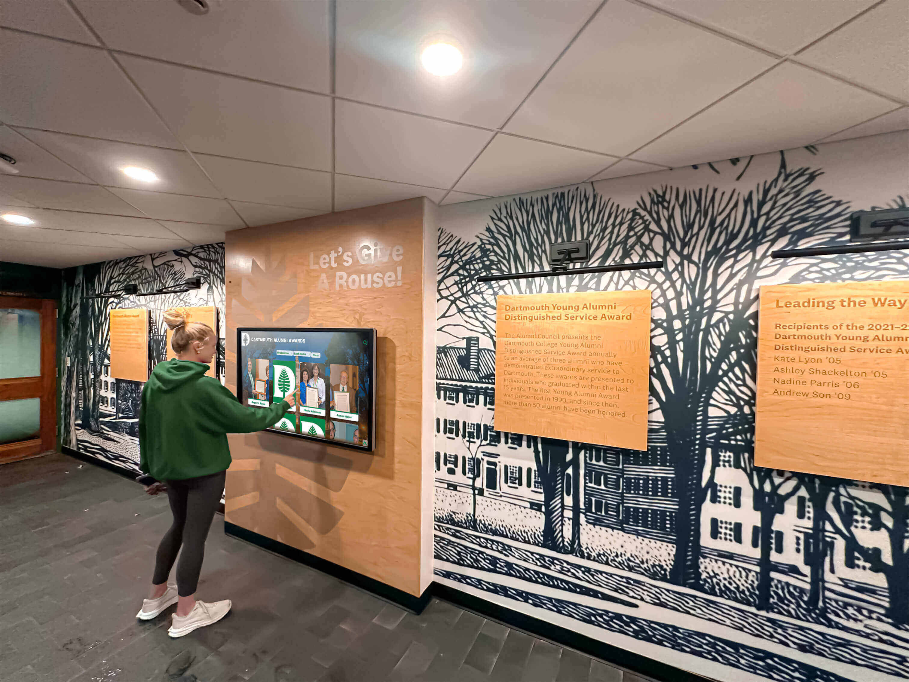
Each display in a multi-unit installation requires an independent Alt Mode test — the same cable may produce different results depending on which source port drives it
How This Test Relates to a Complete Commissioning Sequence
The USB-C Alt Mode test addresses the video, touch, and power signal chain. It does not replace the other commissioning steps that apply before a recognition display goes public. A complete pre-go-live sequence for a school recognition display typically includes:
- Cable continuity test — verifies power, Ethernet, and any supplemental HDMI or USB cables are fault-free before installation. Schools using USB-C as the only cable still need Ethernet continuity verified if the display connects to a cloud-based content management system.
- USB-C Alt Mode test — this checklist.
- Refresh rate test — confirms motion content, scrolling text, and slide transitions play smoothly on the production media player and CMS.
- Content acceptance review — confirms that athlete records, program history, and donor information display correctly and that staff have access to update content through the CMS before the display goes live.
Running these steps in sequence — before mounting, not after — eliminates the most common sources of post-installation service calls on school recognition displays.
Frequently Asked Questions
What is USB-C Alt Mode and why does it matter for a recognition display?
USB-C Alt Mode is a feature of the USB-C specification that allows the connector’s pins to carry non-USB protocols — most commonly DisplayPort video signal, which is called DisplayPort Alt Mode. For recognition displays, Alt Mode enables a single USB-C cable to deliver video, touch data, and power simultaneously, eliminating separate HDMI and USB cables from the installation. It matters because a display that relies on Alt Mode for all three functions fails entirely if any part of the chain — cable, source port, or display port — does not support it.
How do I know whether the source device’s USB-C port supports DisplayPort Alt Mode?
Check the device manufacturer’s specification page for the USB-C port’s declared capabilities. Alt Mode-capable ports are typically labeled with a DisplayPort symbol (a D shape with a cutout) next to the port on the device chassis, or listed as “DP Alt Mode” in the port specification in the product datasheet. A USB-C port labeled only “USB 3.x” or with a charging bolt icon may carry USB data and power but not video. When the specification is unclear, contact the device vendor with the specific port location and ask whether DisplayPort Alt Mode output is supported on that port.
Can we use a USB-C to HDMI adapter instead of a native Alt Mode cable?
A USB-C to HDMI adapter works as a video solution, but it changes the installation from a single-cable Alt Mode setup to a traditional HDMI configuration. Touch data does not travel through the HDMI cable in this configuration — you need a separate USB cable for the touchscreen controller. Power delivery also does not flow through the HDMI path. If using an adapter for video, run a standard HDMI cable continuity test for video and a separate USB touch cable test rather than this Alt Mode checklist.
Our display vendor said one USB-C cable handles everything — why do we still need to test?
Vendor guidance that one cable handles video, power, and touch is accurate when the cable, source port, and display port all meet the required specifications. The test confirms this is the case at the specific installation site with the specific hardware combination being used. Vendor claims apply to the product line generally; this checklist verifies the specific cable, source port, and display port at the specific location. Recognition programs that host athletic award programs and community recognition events benefit from a documented commissioning test regardless of vendor confidence in the product.
How long does the full Alt Mode test take per display?
The full checklist — visual inspection, specification verification, video test, touch test, power delivery test, and 15-minute combination test — takes approximately 45 to 60 minutes per display. The 15-minute combination test accounts for the largest portion of that time. Multi-display installations scale proportionally; a three-display athletics hallway typically takes 2.5 to 3 hours to test fully before mounting begins.
What is the difference between USB-C Alt Mode and Thunderbolt?
Thunderbolt 3 and Thunderbolt 4 use the USB-C connector and include DisplayPort Alt Mode as part of their specification. A Thunderbolt-certified cable will typically pass this Alt Mode test because it supports the required SuperSpeed lanes, USB 2.0 passthrough, and high-wattage USB PD. However, Thunderbolt-specific features — daisy chaining, PCIe tunneling, higher data bandwidth — are not required for recognition display installations. A standard USB 3.2 Gen 2 cable with DP Alt Mode certification is sufficient for most recognition display requirements and typically costs less than a Thunderbolt-certified cable.
Should we test again after the display is mounted?
A brief functional verification after mounting is recommended. Routing the cable around a wall mount bracket or through conduit applies bends near the connector that were not present during the bench test. After mounting, tap the display to confirm touch response, open the OSD to confirm resolution and refresh rate, and check the power meter if applicable. This post-mount check takes under 5 minutes and confirms the routing process did not introduce a mechanical fault.
Does this test apply if the display uses cloud-based content management?
The USB-C Alt Mode test verifies the hardware signal chain: video, touch, and power. Cloud-based content management connectivity depends on the display’s network connection — typically a separate Ethernet or Wi-Fi path — not the USB-C Alt Mode signal. Run the Alt Mode test independently of the network connection, then verify network and CMS access separately once the display passes. For schools planning recognition programs with cloud-driven alumni and awards recognition platforms, confirm that the source device’s network adapter does not share USB bandwidth with the USB-C port used for Alt Mode, since shared bandwidth can cause intermittent touch dropout under high network load on some devices.
A recognition display USB-C Alt Mode test adds 45 to 60 minutes to a school installation and confirms that video, touch, and power all negotiate correctly before the display is mounted. Work through the test steps in the order presented — specification first, video second, touch third, power fourth, sustained combination last — and document every result before mounting. Replace any cable that fails, and verify the source port specification before ordering a replacement. The cost of a compliant cable is always less than the cost of dismounting a wall-hung recognition display to diagnose a connection failure after go-live.
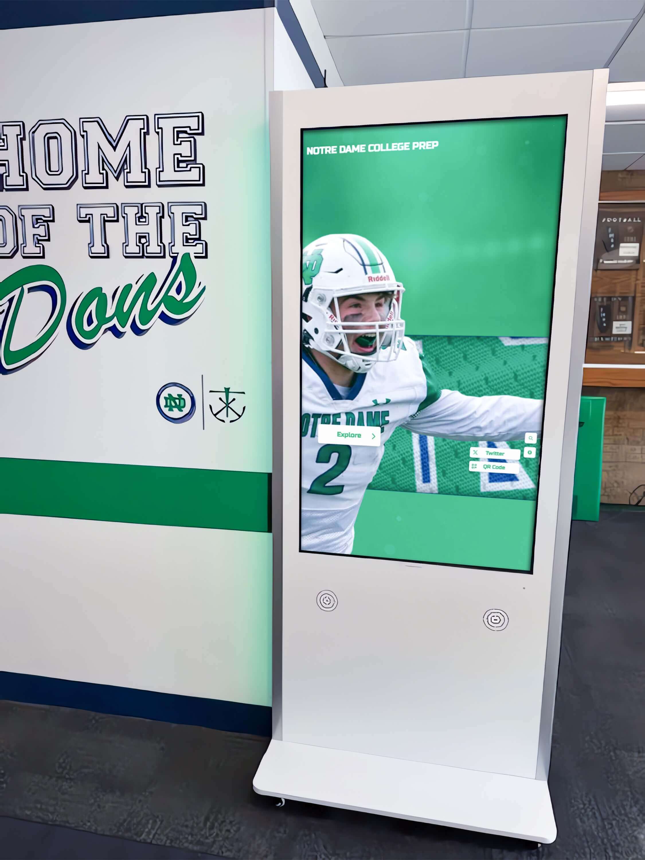
A documented Alt Mode commissioning test ensures the recognition display works correctly on go-live day and gives future IT staff a verified starting point for any troubleshooting
Looking for a recognition display partner that manages hardware commissioning from cable to content? Rocket Alumni Solutions handles the full installation process — including USB-C Alt Mode verification, touch calibration, and content setup — so your school’s hall of fame, athletic record board, or donor wall is ready to run on day one without last-minute troubleshooting. Request a demo to learn how their managed approach handles technical installation details so your team can focus on recognition program content, not cables.