Intent: demonstrate — this checklist walks school IT coordinators and network administrators through a recognition display spanning tree protocol test to confirm that a hall-of-fame kiosk, donor wall screen, or athletic record board transitions to forwarding state quickly enough for the display to obtain a DHCP lease at boot, and that the switch port is protected against accidental loop creation by downstream unmanaged switches or hubs that might be connected to the same location.
A recognition display connects to a managed access switch as a single end-device: it does not forward frames between switches, and it does not participate in spanning tree topology decisions. Yet the switch port serving the display is fully subject to Spanning Tree Protocol (STP) behavior. On a switch running classic IEEE 802.1D STP without PortFast configured on the access port, that port spends up to 50 seconds in the Listening and Learning states before it begins forwarding traffic. During those 50 seconds, the display’s operating system issues DHCP DISCOVER packets that are silently discarded by the switch — the display either boots to a network-unavailable state or obtains an address from the wrong scope after an extended timeout. Running a structured spanning tree compatibility test before the display enters unattended operation confirms that the access port reaches forwarding state within the display’s DHCP timeout window and that the port is protected from loop-related disruption throughout the school year.
The quick answer: verify PortFast is enabled on the display’s access port so the port skips the Listening and Learning states and moves directly to Forwarding, confirm BPDU Guard is enabled on the same port to protect against accidental loop creation if a hub or unmanaged switch is connected in the same area, test that the display obtains a DHCP lease within a normal timeout after a simulated port link-down and link-up cycle, and confirm that a spanning tree topology change notification (TCN) triggered elsewhere in the building does not interrupt the display’s active CMS connection. If any check fails, the port configuration or the VLAN’s STP settings need correction before the display enters unattended operation.
This procedure applies to recognition displays running Windows or Linux on dedicated media PCs, embedded media players, and kiosk-grade appliances connected to managed switches running IEEE 802.1D STP, IEEE 802.1W Rapid STP (RSTP), or IEEE 802.1S Multiple STP (MSTP). The test is the same whether the installation is a 55-inch lobby hall-of-fame kiosk or an 86-inch corridor athletic record board.
A recognition display port that spends 30–50 seconds in STP Listening and Learning states causes DHCP discovery packets to be silently dropped — the display boots to a network-unavailable state with no visible error and no staff member nearby to intervene
What Is Spanning Tree Protocol?
Spanning Tree Protocol (STP), defined in IEEE 802.1D, is a Layer 2 network protocol that prevents switching loops in Ethernet networks by selectively placing switch ports into a Blocking state when redundant paths exist between switches. A switching loop — where the same Ethernet frame circulates through multiple switches indefinitely — would consume all network bandwidth and bring down every device on the affected network segment. STP prevents this by electing a single root bridge and blocking all redundant paths that would create a loop, leaving only one active path between any two points in the network.
Three STP variants are in common use in school networks:
- IEEE 802.1D STP (classic) — the original standard. Port states: Blocking, Listening (15 seconds), Learning (15 seconds), Forwarding. Total convergence after a topology change: 30–50 seconds. Still deployed on older school switching equipment.
- IEEE 802.1W RSTP (Rapid STP) — the modern replacement for classic STP. Convergence after a topology change: typically 1–6 seconds. Port states: Discarding, Learning, Forwarding. Backward-compatible with classic STP. Most switches purchased in the past decade default to RSTP.
- IEEE 802.1S MSTP (Multiple STP) — extends RSTP to support multiple spanning tree instances, each mapping to one or more VLANs. Common in multi-VLAN school environments where load-balancing across redundant uplinks is a goal.
For a recognition display connected to an access port, three STP behaviors directly affect compatibility:
1. Port state transitions at link-up. When the display’s Ethernet cable is connected — at boot, after a cable reconnect, or when the switch port recovers from a shutdown — the port begins the STP state machine from the beginning. On classic STP, the port spends 15 seconds in Listening (during which it does not forward any frames) and 15 seconds in Learning (during which it builds its MAC address table but does not forward user data frames) before reaching the Forwarding state. The display’s DHCP DISCOVER packets are dropped during both states. If the display’s DHCP client times out before the port reaches Forwarding, the display fails to obtain a lease.
2. PortFast. PortFast is a switch feature — available on Cisco IOS, Aruba OS, Juniper EX, and most other managed switch platforms under equivalent names — that instructs the switch to skip the Listening and Learning states for an access port and transition directly to Forwarding when the link comes up. PortFast is the correct configuration for all access ports that connect only end devices (computers, printers, display media PCs), never switches. With PortFast enabled, the port reaches Forwarding in under one second — the display’s DHCP client succeeds on the first attempt.
3. BPDU Guard. Bridge Protocol Data Units (BPDUs) are the frames that STP-capable switches exchange to elect the root bridge and coordinate the spanning tree topology. End devices — including recognition display media PCs — do not generate BPDUs. If a PortFast-enabled access port receives a BPDU — most commonly because someone connected an unmanaged hub or a consumer switch to the same port or outlet strip as the display — BPDU Guard immediately places the port in err-disabled state, preventing any traffic from passing. This is the correct response: it prevents a rogue switch from altering the spanning tree topology and potentially creating a loop. BPDU Guard should be enabled on all PortFast ports, including the recognition display access port.
Why STP Behavior Matters for School Recognition Displays
A hall-of-fame kiosk, athletic record board, or donor wall screen installed in a school lobby has operational characteristics that make STP compatibility particularly important.
The display reboots on a schedule without a user present. Recognition displays commonly start on an automated power schedule — powering on before school opens, shutting down after hours. Each power cycle brings the switch port through the link-down and link-up cycle, restarting the STP state machine. On a port without PortFast, every scheduled reboot produces a 30–50 second window where DHCP packets are dropped. Schools that rely on recognition displays to announce scheduled events and daily updates need the display fully connected before staff and students arrive — a multi-minute STP delay at boot defeats that goal.
The display holds a fixed, unattended position. A recognition display in a public hallway or lobby is accessible to visitors, vendors, and students who may connect laptop chargers, surge protectors with pass-through network ports, or unmanaged hubs to the same power outlet strip as the display. Any of these devices might have a built-in network switch that generates BPDUs. BPDU Guard on the display access port converts this otherwise invisible misconfiguration into an immediate, detectable err-disabled event that alerts IT staff before any loop is created.
STP topology changes elsewhere in the building affect the display VLAN. When any switch port in the building transitions from Forwarding to Blocking or vice versa — because an uplink switch failed, a cable was disconnected, or a new switch was connected during maintenance — the spanning tree generates a Topology Change Notification (TCN). In classic STP, TCNs cause all switches in the spanning tree to flush their MAC address tables, temporarily flooding traffic until the tables are rebuilt. Schools that display recognition awards and achievement content to visitors throughout the day depend on CMS content delivery staying stable even during network maintenance events in other parts of the building.
Summer network work resets switch configurations. Access switches replaced or firmware-updated during summer often reset port configurations to defaults. A default access port on most managed switches does not have PortFast enabled — it runs the full STP state machine. IT staff who verify connectivity by plugging a laptop into the display port after a switch replacement may see the port come up and pass traffic (laptops typically wait longer for network access than display DHCP clients), missing the STP delay problem that will surface when the display reboots on its automated schedule on the first day of school.
Spanning Tree Protocol Decision Tree for Recognition Display Ports
Use this decision tree before the detailed checklist to identify the most important configuration gaps.
1. What STP mode is running on the switch?
- Classic STP (802.1D) → PortFast is critical; the 30–50 second convergence window will exceed most DHCP client timeouts
- RSTP (802.1W) → PortFast still recommended; RSTP converges in 1–6 seconds but PortFast provides sub-second convergence
- MSTP (802.1S) → treat the same as RSTP for access port behavior; check which instance maps to the display VLAN
↓
2. Is PortFast enabled on the display’s access port?
- NO → enable PortFast on the port and retest; DHCP acquisition should succeed within 1–2 seconds of link-up
- YES → continue
↓
3. Is BPDU Guard enabled on the display’s access port?
- NO → enable BPDU Guard on the same port and confirm it does not trigger immediately (which would indicate an unexpected BPDU source already connected to the port)
- YES → continue
↓
4. Does the display obtain a DHCP lease within 30 seconds of link-up?
- NO with PortFast enabled → check for BPDU Guard err-disabled state; check for DHCP snooping rate limiting (covered in a separate checklist); confirm DHCP server reachability
- YES → continue
↓
5. Does a simulated STP topology change notification interrupt the display’s active CMS connection?
- YES → MAC table flushing during TCN is causing brief traffic interruption; investigate root guard and TCN filtering options on the display VLAN uplink
- NO → continue
↓
6. Result: STP is compatible with this display port — proceed to the full checklist
Tools Required
| Tool | Use | Notes |
|---|---|---|
| Switch CLI access (SSH or console) | Run STP show commands (show spanning-tree, show spanning-tree interface, show interfaces status) to verify port state, PortFast configuration, and BPDU Guard status | Administrative access required; Cisco IOS syntax used as the primary reference throughout this checklist; Juniper EX and Aruba/HP ProCurve equivalents noted where they differ |
| Windows PowerShell or CMD (display media PC) | Run ipconfig /release and ipconfig /renew to trigger DHCP cycles; run ping and Test-NetConnection to confirm connectivity after each test step | Available on all Windows 10/11 installations; simulates the display's boot-time network requests without requiring a physical reboot for most test steps |
| A second laptop or switch (for BPDU Guard test) | Temporarily connect a device that generates BPDUs — a managed switch or a laptop running a network emulator — to the display access port to verify BPDU Guard triggers correctly | Required only for Step 4 (BPDU Guard verification); use a spare managed switch from IT inventory; an unmanaged switch does not generate BPDUs and cannot trigger BPDU Guard |
| Network documentation (switch port assignments, STP mode) | Identify the access switch model, the STP variant running on the switch, the specific port serving the display, and the display VLAN ID before beginning the test | Required before testing; confirm from the school's network documentation or by running show spanning-tree on the access switch |
| CMS management portal | Confirm the display appears online after each test step and that the last content synchronization timestamp is current; verify the display reconnects within an expected window after a simulated link cycle | Application-layer confirmation that STP convergence time does not prevent the display from successfully reaching the cloud CMS after each boot or reconnect event |
| Stopwatch or timer | Measure elapsed time from link-up to successful DHCP lease acquisition; compare to the DHCP client timeout configured on the display's operating system | Critical for confirming PortFast is working; without a timer, a 45-second STP delay can appear to be a slow-but-functional DHCP acquisition |
Pre-Test: Document the STP Baseline Configuration
Before testing, record the current STP configuration for the display access port so each test step has a clear expected result.
- Log into the access switch via SSH or console. Run
show versionto confirm the switch model and software version — this determines which STP variant and CLI syntax apply. - Run
show spanning-treeto identify the active STP mode (STP, RSTP, or MSTP) and the root bridge for the display VLAN. Record the root bridge address and priority, and the current port role and state for the display port. - Run
show spanning-tree interface <port-id> detailto check whether PortFast is configured and whether BPDU Guard is enabled on the display access port. - Run
show interfaces <port-id> statusto confirm the port is currently in a connected (forwarding) state and not in err-disabled. - From the display media PC, run
ipconfig /alland record the current IP address, MAC address, default gateway, and DNS servers. This baseline confirms the display currently has a valid lease before the test begins. - Log into the CMS management portal and note the display’s last synchronization timestamp. This gives you a comparison point after each test step.
Record all six items before beginning Step 1 of the checklist.
Recording the switch model, STP mode, and current port configuration before testing ensures each checklist step has a specific pass criterion rather than an ambiguous result
Recognition Display Spanning Tree Protocol Test Checklist
Step 1: Identify the STP Mode Running on the Display VLAN
Confirm which spanning tree variant is active on the VLAN serving the recognition display, and understand what convergence behavior to expect.
- Log into the access switch and run:
show spanning-tree vlan <VLAN_ID> - In the output header, locate the Spanning tree enabled protocol line. The value will be one of:
ieee(classic 802.1D STP),rstp(802.1W RSTP), ormstp(802.1S MSTP). - Note the Root ID section — specifically the Root bridge is the or This bridge is the root line. If the access switch serving the display is the root bridge, topology changes initiated by that switch will directly affect the display VLAN rather than propagating from a remote switch.
- Note the Hello Time, Max Age, and Forward Delay timer values. On classic STP, the Forward Delay is typically 15 seconds and applies twice (Listening + Learning), giving 30 seconds of blocked forwarding. On RSTP, the equivalent transitions are negotiated rapidly and typically complete in under 6 seconds even without PortFast.
- On Juniper EX:
show spanning-tree interfaceandshow spanning-tree bridgeprovide equivalent output. On Aruba/HP ProCurve:show spanning-tree <port-id>shows per-port STP state.
Record the STP mode and the Forward Delay value.
Pass criteria: STP mode documented; forward delay and convergence behavior understood for the switch vendor and mode in use.
Step 2: Verify PortFast Is Enabled on the Display Access Port
Confirm that the display’s access port is configured to skip the STP Listening and Learning states and transition directly to Forwarding when the link comes up.
- On the access switch, run:
show spanning-tree interface <port-id> detail - In the output, locate the The port is in the portfast mode line or equivalent. On Cisco IOS this appears as
The port is in the portfast modewhen PortFast is enabled. - If PortFast is not enabled, add it to the interface:
interface <port-id>
 spanning-tree portfast
On Juniper EX: set interfaces ge-0/0/X unit 0 family ethernet-switching interface-mode access with set protocols rstp interface ge-0/0/X edge. On Aruba/HP ProCurve: spanning-tree <port-id> admin-edge-port.
4. After enabling PortFast, simulate a link-down and link-up cycle by disconnecting and reconnecting the display’s Ethernet cable (or using shutdown and no shutdown on the interface). Start a timer at link-up.
5. Immediately after link-up, run show spanning-tree interface <port-id> and confirm the port state is FWD (Forwarding) within 1–2 seconds. Without PortFast, the port shows LIS (Listening) or LRN (Learning) for the first 30 seconds.
Pass criteria: Port state reaches Forwarding within 2 seconds of link-up; show spanning-tree interface confirms PortFast mode enabled.
Step 3: Confirm the Display Obtains a DHCP Lease Within the DHCP Timeout Window
With PortFast confirmed, verify that the display’s DHCP client successfully acquires a lease during the time the port is in a Forwarding state after a cold reconnect.
- From the display media PC, open PowerShell as administrator. Run:
ipconfig /releaseto release the current lease. - Simultaneously disconnect the display’s Ethernet cable from the switch port (or run
shutdownon the interface from the switch CLI). Start a timer. - After 5 seconds, reconnect the cable (or run
no shutdownon the interface). Note the time from reconnect — this is when the link-up event occurs. - Run on the display:
ipconfig /renewand note how many seconds elapsed from cable reconnect to successful IP address assignment. - With PortFast enabled, the display should obtain a lease within 3–10 seconds of link-up (network-side delay plus DHCP exchange time). Without PortFast on a classic STP switch, DHCP discovery will fail for the first 30 seconds.
- Run
show spanning-tree interface <port-id>on the switch immediately after the reconnect to confirm the port entered Forwarding state before the DHCP exchange completed.
Pass criteria: Display obtains a valid DHCP lease within 30 seconds of cable reconnect; switch port in Forwarding state before the DHCP ACK is received.
Step 4: Verify BPDU Guard Is Enabled and Responds Correctly
Confirm that BPDU Guard is configured on the display access port and that it correctly transitions the port to err-disabled when it receives a BPDU — protecting the network from accidental loop creation.
- Check the current BPDU Guard configuration on the display port:
show spanning-tree interface <port-id> detail
Look for BPDU guard is enabled in the output. On Cisco IOS, BPDU Guard can be enabled globally on all PortFast ports (spanning-tree portfast bpduguard default) or per-interface (spanning-tree bpduguard enable).
2. If BPDU Guard is not enabled, add it:
interface <port-id>
 spanning-tree bpduguard enable
- To verify BPDU Guard triggers correctly, temporarily connect a managed switch (one that generates BPDUs) to the display access port. Within a few seconds, the port should transition to err-disabled state. Run
show interfaces <port-id> statusand confirm the port shows err-disabled. - Disconnect the managed switch and recover the port:
interface <port-id>
 shutdown
 no shutdown
Optionally configure automatic err-disabled recovery for BPDU Guard events: errdisable recovery cause bpdu-guard with errdisable recovery interval 300. A 300-second auto-recovery interval means the port re-enables itself after 5 minutes — useful for display ports where IT staff may not be immediately available to manually recover the port after a BPDU event.
5. After the port recovers, confirm the display re-obtains its DHCP lease (it will go through the PortFast transition again and acquire an address quickly) and that the CMS portal shows the display back online.
Pass criteria: BPDU Guard enabled on the display access port; port transitions to err-disabled within 5 seconds of a managed switch being connected; port recovers and display re-connects successfully after the managed switch is removed.
Step 5: Test STP Topology Change Notification Impact on the Display
Confirm that a topology change in another part of the network does not interrupt the display’s active CMS connection for more than a brief, acceptable window.
- Note the display’s current active CMS connection and the last synchronization timestamp in the CMS portal.
- To simulate a TCN, disconnect and reconnect an uplink cable between two access switches elsewhere in the building (not the switch directly serving the display). This triggers a Topology Change Notification that propagates to all switches in the spanning tree.
- On classic STP, a TCN causes the root bridge to set the Topology Change flag in BPDUs for a period equal to the Forward Delay + Max Age (typically 35 seconds), during which all switches flush their MAC address tables more aggressively. Monitor the display’s CMS connection status during this window.
- On RSTP, the TC handling is per-port and localized — TCNs flush only the MAC entries for the specific port that changed, not the entire MAC table. The display’s connectivity should be unaffected by a remote TCN on an RSTP network.
- After 60 seconds, confirm the display’s CMS connection remains active or has recovered. If the display shows as offline in the CMS portal for more than 10–15 seconds during the TCN, investigate whether the access switch serving the display is flushing its full MAC table on each TCN rather than handling them per-port (indicating a classic STP rather than RSTP behavior).
Schools that program competitive sports recognition displays and digital championship records for continuous public visibility need the display to remain online even when IT teams are performing scheduled network maintenance in adjacent parts of the building.
Pass criteria: CMS connection remains active or recovers within 15 seconds after a remote TCN; no lasting disruption to display content delivery.
Step 6: Confirm Root Guard on Uplink Ports (Multi-Switch Environments)
In schools with multiple access switches, verify that root guard is configured on the uplink ports connecting the access switch to the distribution layer so that a misconfigured downstream switch cannot become the root bridge and alter the spanning tree topology affecting the display VLAN.
- On the access switch, run:
show spanning-tree interface <uplink-port-id> detail - Look for Root guard is enabled in the output. Root guard prevents the port from becoming a Root port — if a superior BPDU (one that would trigger a root bridge election change) is received on a root-guard-enabled port, the port is placed in a Root-inconsistent state rather than allowing the topology change.
- If root guard is not enabled on uplink ports:
interface <uplink-port-id>
 spanning-tree guard root
- Root guard is complementary to BPDU Guard: BPDU Guard protects access ports (where no BPDUs should arrive), while root guard protects uplink ports (where BPDUs arrive legitimately but should never represent a superior root bridge offer from downstream).
- Confirm that root guard is not enabled on the display’s own access port — root guard belongs on uplinks, not access ports. The display’s access port should have BPDU Guard, not root guard.
Pass criteria: Root guard enabled on uplink ports serving the display VLAN; root guard absent from the display’s own access port (where BPDU Guard applies instead).
Step 7: Record Results and Make a Go / No-Go Decision
Document the full spanning tree protocol compatibility test before releasing the display to unattended operation.
| Test Item | Expected Result | Actual Result | Pass / Fail | Tested By | Date |
|---|---|---|---|---|---|
| STP mode identified | STP variant documented (STP/RSTP/MSTP); Forward Delay recorded | ||||
| PortFast enabled on display access port | Port reaches Forwarding state within 2 seconds of link-up | ||||
| DHCP lease acquired after cold reconnect | Display obtains valid IP within 30 seconds of cable reconnect | ||||
| BPDU Guard enabled on display access port | Port enters err-disabled state when a managed switch is connected | ||||
| BPDU Guard recovery | Port recovers and display re-connects after managed switch removed | ||||
| TCN impact test | CMS connection active or recovered within 15 seconds after remote TCN | ||||
| Root guard on uplink ports | Root guard enabled on uplinks; absent from display access port |
Go / No-Go rule: All seven items must show a passing result before the display enters unattended operation. A display whose access port lacks PortFast will fail to obtain a DHCP lease on most scheduled reboots and should not be placed in an unattended public location until PortFast is configured. A display port without BPDU Guard creates an unprotected loop risk that should be corrected before any public installation.
A completed STP compatibility record documents the PortFast and BPDU Guard configuration for the display port, giving network administrators a verified baseline to restore if a switch replacement resets the port to defaults
Troubleshooting: Common STP Compatibility Failures
| Symptom | Probable Cause | Resolution |
|---|---|---|
| Display fails to obtain DHCP lease at boot; port eventually connects but DHCP times out first | PortFast not enabled on the access port; port spends 30–50 seconds in Listening and Learning states before reaching Forwarding; display DHCP client times out before DHCP packets are forwarded | Enable PortFast on the display access port: interface <port-id> → spanning-tree portfast. Retest lease acquisition with a timer — with PortFast enabled, the port reaches Forwarding in under 2 seconds and the display should obtain a lease in under 10 seconds |
| Display access port enters err-disabled state unexpectedly without any physical change | BPDU Guard triggered by a device connected near the display — a consumer router, an unmanaged switch acting as a BPDU pass-through, or a laptop with a virtual switch adapter — generating BPDUs on the access port | Investigate what is connected to the outlet strip or patch panel near the display. Run show interfaces <port-id> status to confirm err-disabled and show logging to find the BPDU Guard event timestamp. Remove the BPDU-generating device. Recover the port with shutdown/no shutdown. Consider configuring errdisable recovery for bpdu-guard with a 300-second interval so the port auto-recovers if the BPDU source is removed before IT arrives |
| PortFast enabled but display still takes 30+ seconds to connect after reboot | The access switch is running classic STP globally and the PortFast configuration is being overridden by a global or VLAN-level STP setting; or the display's NIC driver is delaying the DHCP request, not the STP port state | Run show spanning-tree interface <port-id> detail and confirm The port is in the portfast mode appears. If PortFast is confirmed but the delay persists, use a packet capture on the display to determine whether DHCP DISCOVERs are being sent and whether responses are received — the delay may be in the application layer, not the switch |
| Display loses CMS connection for 30–60 seconds after another switch in the building is rebooted | Classic STP topology change notification causing all switches to flush MAC address tables; traffic to the display is flooded rather than forwarded directly until the MAC table rebuilds | Confirm whether RSTP is enabled on all switches in the spanning tree path. A mixed STP/RSTP environment where the access switch runs RSTP but a distribution switch runs classic STP causes RSTP convergence to fall back to classic STP timers. Upgrade all switches to RSTP mode to eliminate 30-second TCN-driven MAC table flush delays |
| Root guard triggers Root-inconsistent state on an uplink port, cutting off the display VLAN | A switch connected downstream (possibly a new access switch installed during maintenance) is advertising a superior root bridge priority, triggering root guard on the uplink where it is configured | Run show spanning-tree vlan <VLAN_ID> and identify which port is in Root-inconsistent state. Investigate the downstream switch's STP priority — it may have been configured with a lower bridge priority than the intended root bridge. Correct the downstream switch's STP priority to a value higher than the intended root bridge, or explicitly set the correct root bridge with spanning-tree vlan <VLAN_ID> priority 4096 on the intended root bridge |
| Display port enters err-disabled immediately after PortFast and BPDU Guard are both enabled | A device already connected to the port (or in the same physical location on a shared cable run) is generating BPDUs; BPDU Guard triggers the moment PortFast is enabled and the port re-initializes | Temporarily disable BPDU Guard while diagnosing: no spanning-tree bpduguard enable. Run debug spanning-tree bpdu receive and check the source MAC address of incoming BPDUs. Trace the cable run to identify the BPDU-generating device. Remove it before re-enabling BPDU Guard |
| School adds a second display to the same room; both display ports now generate err-disabled events intermittently | A patch panel, outlet strip, or structured wiring hub connecting both displays to the same jack is creating a loop between the two display ports through a non-STP-capable device; loop traffic triggers BPDU Guard on one or both ports | Trace the physical path for each display to confirm each terminates at its own dedicated access port. Two displays sharing a single network jack through an unmanaged hub create a bridging loop. Each display must connect to its own dedicated access switch port. Review the wiring with the facilities team if the installation used shared runs |
Post-Test Steps Before Returning to Unattended Operation
After all test items pass, complete these steps before closing the commissioning session.
Save the switch configuration. On Cisco IOS, run
write memoryorcopy running-config startup-configto save the PortFast, BPDU Guard, and root guard configurations to the switch’s startup config. A power loss or unexpected reboot would otherwise lose all configuration changes made during testing.Document the port configuration in the display’s commissioning record. Record the switch name, port ID, STP mode, PortFast status, BPDU Guard status, and VLAN alongside the display’s serial number and physical location. If the access switch is replaced during summer maintenance, this record is the baseline the replacement switch should match. Schools that host intramural sports and multi-program recognition displays across multiple athletic venues need IT staff to be able to restore a correct switch configuration for any display port from a single reference document rather than re-testing each port from scratch.
Add a port description to the switch. Apply a port description identifying the port as the recognition display connection. On Cisco IOS:
interface <port-id>
 description Recognition-Display-Lobby-PortFast-BPDUGuard
Port descriptions appear in SNMP monitoring output and switch show commands, making future identification faster without reference to the asset documentation.
- Confirm CMS connectivity and synchronization. After the final PortFast and BPDU Guard verification, open the CMS management portal and confirm the display appears online with a current synchronization timestamp. A passing STP test record means nothing if the display’s application layer lost contact with the CMS during the testing process and has not recovered. Schools with continuous recognition programs need CMS sync confirmed before the display returns to its public-facing schedule.
Looking for a recognition display partner that arrives with network-ready configuration guidance — including switch requirements, PortFast and BPDU Guard recommendations, and ongoing remote monitoring — for your school’s hall-of-fame or athletic record board installation? Rocket Alumni Solutions manages the complete deployment and ongoing remote support for school recognition display programs so IT teams focus on their own priorities rather than display network troubleshooting. Request a network-ready demo to see how their managed approach handles switch configuration requirements from the start.
- Schedule a post-summer verification. Add a note to the school’s IT maintenance calendar to confirm PortFast and BPDU Guard are still enabled on the display access port at the start of each school year, particularly after any access switch replacement, firmware update, or configuration baseline reset. A switch restored from a vendor factory default during summer maintenance will not have PortFast or BPDU Guard — the display will boot to a network-unavailable state on the first day of school without a pre-season configuration check.
Recording switch port configuration in the display's commissioning document allows IT staff to restore the correct PortFast and BPDU Guard settings after any summer switch replacement without repeating the full test procedure
STP Considerations for Multi-Display School Installations
Schools running recognition displays in multiple locations — a main lobby hall-of-fame wall, an athletics corridor record board, a gymnasium scoreboard display, and a donor recognition panel in the administrative wing — face additional STP considerations that go beyond the single-port test.
Each display port must be tested independently. A passing STP result on one access switch does not guarantee the same configuration exists on other switches. Access switches in different parts of a school building may have been installed or firmware-updated at different times, leaving inconsistent PortFast and BPDU Guard configurations across the building. Run Steps 1 through 6 on each display port independently.
Simultaneous scheduled reboots amplify TCN impact. If all recognition displays across a school are set to power on at the same time in the morning — common with smart UPS outlet switching or scheduled power management — each display reconnecting simultaneously generates multiple port link-up events within a short window. On classic STP, each link transition is a potential TCN. Stagger display power-on times by 30–60 seconds between locations to reduce simultaneous TCN generation, or upgrade all switches to RSTP to eliminate the 30-second TCN window.
Multi-building campuses with fiber uplinks. Schools with separate buildings connected by fiber uplinks typically have a spanning tree root bridge at the district or campus core switch. The path from the display access port through the access switch, distribution switch, and core switch is the full STP topology scope. A topology change in one building’s access layer can propagate TCNs to display VLANs in other buildings. Confirm that TCN filtering (Cisco: spanning-tree portfast bpdufilter default at the edge, or RSTP per-port TC propagation control) is consistently configured at the distribution layer to limit TCN propagation scope to the originating access switch rather than the full campus spanning tree.
Portable or temporary displays at seasonal events. Some schools bring recognition displays to gymnasiums, auditoriums, or outdoor pavilions for awards programs and recognition events. When these displays are connected to event-space switch ports that may not have PortFast configured, the same DHCP-timeout failure observed on permanent display ports will occur. Create a standard port template for event-space ports used by recognition displays and apply it consistently to every port in the event infrastructure.
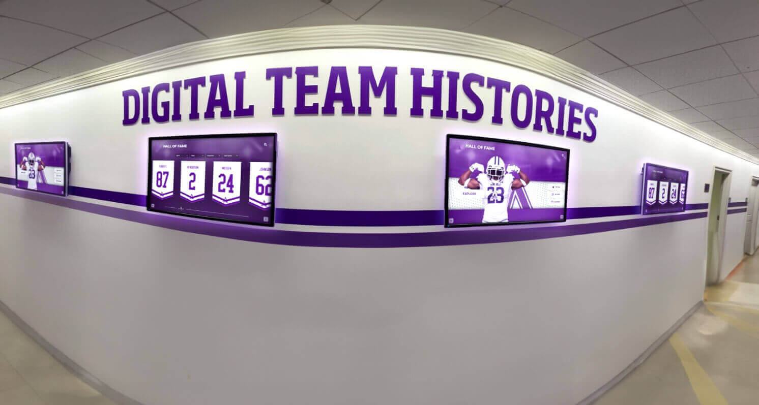
Schools running recognition displays across multiple hallways and access switches should apply a standard PortFast and BPDU Guard template to every display access port — inconsistent configurations across switches are the most common source of intermittent boot failures in multi-display deployments
Frequently Asked Questions
Why does my recognition display connect fine when I plug a laptop into the same port, but the display itself fails to connect after a reboot?
Laptops and general-purpose computers typically have longer network timeout windows than the fixed DHCP client behavior on a dedicated media PC or embedded display player. A laptop DHCP client may retry DISCOVER packets for 60–120 seconds — long enough to eventually succeed after the 30–50 second STP Listening and Learning phase completes. A display media PC or embedded player may have a shorter DHCP timeout configured, causing it to give up before the STP convergence completes and report a network failure. This discrepancy is the most common reason IT staff miss the STP PortFast problem during commissioning — they test with a laptop, everything works, and the display later fails. Always test using the actual display hardware after a PortFast change, not with a test laptop.
Should PortFast be enabled globally on all access ports or only on the display port?
Enabling PortFast globally on all access ports — using spanning-tree portfast default on Cisco IOS — is a common and supported configuration that eliminates per-port configuration for every access port in the building. The safety mechanism is BPDU Guard: with BPDU Guard also enabled globally (spanning-tree portfast bpduguard default), any port that receives a BPDU transitions to err-disabled immediately, preventing the loop risk that PortFast would otherwise create if a switch were connected to a PortFast port. Applying both globally is a common baseline configuration for school access switches, but confirm with the network administrator before applying — global changes affect all access ports simultaneously.
What is the difference between BPDU Guard and BPDU Filter?
BPDU Guard places a port in err-disabled state when it receives a BPDU, preventing the BPDU-generating device from altering the spanning tree topology. BPDU Filter suppresses BPDUs in both directions on a port — it neither sends nor receives BPDUs, effectively removing the port from the spanning tree entirely. BPDU Filter is appropriate only in specific, well-understood topologies such as provider edge ports or multi-vendor STP boundary configurations. For recognition display access ports, BPDU Guard is the correct choice — it protects against accidental loop creation while still allowing STP to monitor the port for anomalous behavior. BPDU Filter on a display port would prevent detection of a rogue switch connected to the port.
Does enabling PortFast on the display port affect STP for other devices on the same VLAN?
No. PortFast is a per-port behavior that affects only the individual port’s transition through STP states. It does not change the spanning tree topology, the root bridge election, or the forwarding behavior of any other port on the VLAN. PortFast does suppress Topology Change Notifications from the PortFast-enabled port — if a PortFast port transitions from link-down to link-up (as a display does on each reboot), a TCN is not generated, which is the correct behavior for end-device access ports and avoids unnecessary MAC table flushes across the building.
What happens to the display’s STP configuration when the access switch is replaced during summer maintenance?
A replacement switch delivered with factory defaults will not have PortFast or BPDU Guard configured on any port. When the display reconnects to the replacement switch for the first time, the port runs the full STP state machine — 30–50 seconds of blocking before forwarding — and the display fails to obtain a DHCP lease on its first boot. The recovery is straightforward: log into the new switch, locate the display’s access port, enable PortFast and BPDU Guard, save the configuration, and document the change. The commissioning record from the original installation is the reference document for these changes. Schools that maintain their recognition display port configuration in an IT asset record can restore the correct settings in under five minutes; schools without documentation may spend an hour troubleshooting what appears to be a network or display hardware failure.
How does STP interact with DHCP snooping on the display port?
Both STP and DHCP snooping operate at Layer 2 and both have mechanisms that can prevent a display from obtaining a DHCP lease: STP through the Listening/Learning state delay, and DHCP snooping through port rate limiting and binding table misconfiguration. They are independent features that must each be configured correctly. A display port with PortFast enabled but without the DHCP snooping trust and rate-limit configuration set correctly will still fail DHCP acquisition — PortFast addresses the STP convergence timing issue; it does not affect DHCP snooping behavior. Run the DHCP snooping compatibility checklist separately from this STP test to address both independently.
A recognition display’s Layer 2 network behavior during boot is only reliable when the access switch port is configured to forward traffic immediately rather than waiting for the full STP convergence cycle. Running this recognition display spanning tree protocol test at commissioning — and verifying the configuration after any summer switch replacement — confirms that PortFast skips the Listening and Learning delay, BPDU Guard protects against accidental loop creation, and TCN-driven MAC table flushes from other parts of the building do not disrupt the display’s active CMS connection. Record PortFast status, BPDU Guard status, DHCP lease acquisition time, and TCN impact result before the display enters its live recognition program schedule.
Interested in a recognition display solution that comes with documented switch configuration requirements — including PortFast, BPDU Guard, and VLAN guidelines — so your IT team can commission the network correctly the first time? Rocket Alumni Solutions deploys hall-of-fame displays and athletic recognition systems for schools with complete network configuration guidance, hardware compatibility documentation, and ongoing remote monitoring support throughout the school year. Schedule a demo to see how Rocket Alumni Solutions makes recognition display deployment straightforward for school IT teams and program administrators.