Intent: demonstrate — this recognition display EMI interference test guide walks school IT coordinators, facilities managers, AV technicians, and athletic directors through identifying, isolating, and resolving electromagnetic interference that produces phantom touches, signal drops, or display instability on a hall-of-fame, donor wall, or athletic record board touchscreen before it goes live in front of students, families, and community members.
Electromagnetic interference (EMI) is electrical noise that radiates from motors, lighting ballasts, PA amplifiers, power cables, and other electrical equipment and couples into nearby sensitive electronics. On a capacitive touchscreen, EMI causes the touch digitizer to register touches that were never made, miss touches that were, or drift the touch registration point away from the correct location. On the display’s video chain, EMI-induced noise produces visible artifacts — flickering, intermittent signal loss, or color fringing — that appear and disappear depending on which electrical systems in the building are active at any given moment. School buildings are among the most EMI-dense environments a recognition display will ever be installed in, because they concentrate lighting, HVAC, PA, bell, elevator, and network switching equipment in the same corridors where recognition displays are typically mounted.
The quick answer: a recognition display EMI interference test maps all significant electrical interference sources within ten feet of the display, then confirms under real operating conditions — with hallway lights cycling, the PA system active, and HVAC running — that the touchscreen registers no phantom touches, no missed intentional touches, and no video signal artifacts. Any persistent failure under these conditions requires electrical isolation work — shielded cable replacement, ground verification, source separation, or conduit bonding — before the recognition program launches.
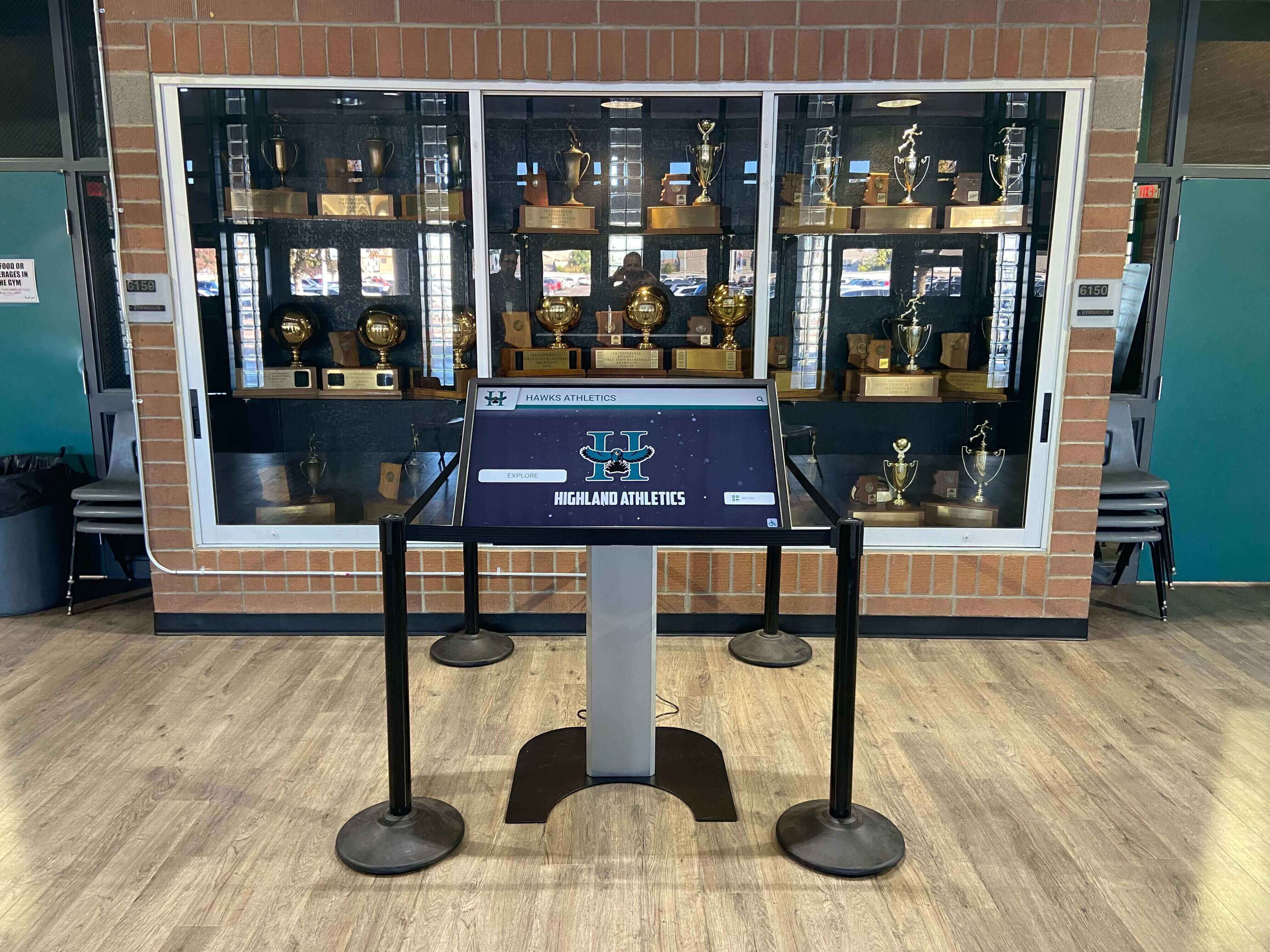
Trophy alcoves and lobby walls concentrate wiring, lighting, and HVAC equipment near the display — making EMI testing essential before a school recognition program launches to the community
What Is EMI Interference on a Recognition Display?
Electromagnetic interference describes unwanted electrical energy that radiates from a source, travels through air or conductive paths, and couples into circuits that were not designed to receive it. Recognition displays contain two categories of circuits that are vulnerable to EMI in a school environment: the capacitive touch digitizer and the video signal chain.
Capacitive touch digitizer susceptibility. A capacitive touchscreen measures tiny changes in the electrical field at the screen surface created when a finger — or any conductive object, including a floating electrical field — approaches the glass. The touch controller samples this field thousands of times per second and interprets changes above a defined threshold as a touch event. EMI that is strong enough or tuned to a frequency that the digitizer’s filtering cannot reject appears to the controller as a legitimate touch event. The result is a phantom touch: the display responds as if a finger pressed a point that no one touched. Phantom touches are disorienting on a recognition interface — the display navigates away from a portrait card, resets to the home screen, or activates a zoom function while a visitor is reading an athlete’s biography.
Video signal chain susceptibility. HDMI, DisplayPort, and USB cables carrying video signals between the media player and the display are transmission lines that act as antennas if their shielding is incomplete or their ground reference is floating. EMI that couples into the video cable produces visible artifacts: horizontal banding that appears when the PA system fires, flickering that tracks the cycle frequency of fluorescent ballasts, or intermittent signal loss that correlates with elevator motor starts in adjacent mechanical rooms.
Three coupling mechanisms are relevant to school recognition display installations:
Radiated EMI originates from electrical equipment and radiates as electromagnetic waves through open air. It is proportional to the distance from the source — moving the display farther from a fluorescent ballast panel or a PA amplifier rack reduces the radiated field. Sources within three feet of a display are the most significant.
Conducted EMI travels along shared electrical wiring. A noisy motor on the same branch circuit as the display injects voltage spikes directly into the display’s power supply. Branch circuit separation — putting the display on a dedicated circuit away from HVAC and PA equipment — eliminates this path.
Inductively coupled EMI occurs when a high-current cable runs parallel to a signal cable for a significant length. HVAC power wiring running parallel to an HDMI cable inside a wall cavity can induce noise into the signal cable even when the cables are not on the same circuit.
EMI Source Reference Table for School Environments
The table below maps the most common EMI sources in school buildings to their typical interference mechanism, the display symptom they produce, and the first isolation step.
| EMI Source | Coupling Mechanism | Typical Display Symptom | First Isolation Step |
|---|---|---|---|
| Fluorescent / T8 ballasts in hallway fixtures | Radiated, 20–50 kHz ballast switching frequency | Phantom touches, especially near top edge of display; fine horizontal banding on video | Test with hallway lights off; replace fluorescent fixtures with LED fixtures using shielded drivers if symptom clears |
| LED driver modules (non-shielded) | Radiated, conducted; switching harmonics 100 kHz–1 MHz | Intermittent phantom touches; HDMI flicker correlated with lighting state changes | Verify LED drivers are Class B rated; add ferrite cores to LED driver output wiring near display |
| HVAC fan and compressor motors | Conducted via shared branch; radiated at motor start | Display flicker or brief touch unresponsiveness at HVAC motor starts; conducted noise on power supply | Verify display is on a dedicated circuit; add a power conditioner or UPS with EMI filtering between wall outlet and display |
| PA system amplifiers and speaker lines | Radiated from amplifier chassis; conducted if on shared circuit | Phantom touches or video flicker during PA announcements; audio-frequency banding on display if PA cable runs parallel to HDMI | Increase separation between PA amplifier and display; route HDMI cable away from speaker wire runs; use shielded HDMI cable |
| Bell system and clock wiring | Conducted transient; brief high-voltage pulse on bell ring | Single phantom touch or brief touch lockup correlated with bell rings | Route bell wiring away from display power and signal cables; verify bell transformer is not on display circuit |
| Elevator motors (adjacent mechanical room) | Conducted and radiated at motor start/stop | Periodic video signal dropout or touch glitch every several minutes matching elevator use patterns | Install EMI-filtering power conditioner; use optical fiber for video delivery if elevator shaft is adjacent to cable run |
| Network PoE switches and server room equipment | Conducted on Ethernet cable; radiated from switching power supplies | Ethernet-coupled touch noise appearing as edge phantom touches; HDMI artifacts if Ethernet and HDMI share conduit | Separate Ethernet and HDMI in conduit by at least 6 inches; use shielded Cat6A (STP) cable with proper grounding at both ends |
| Gym dimmer / scorecard lighting control | Conducted via shared neutral; radiated switching noise | Touch sensitivity drift or phantom touches correlated with gymnasium lighting events | Verify display is on a branch circuit upstream of the dimmer load; add EMI filter on display power supply input |
The Recognition Display EMI Interference Test: Step-by-Step Procedure
The following procedure requires no specialized EMI measurement equipment. It uses behavioral observation — watching the display’s touch response and video output while systematically activating and deactivating electrical sources — to identify interference coupling paths that require isolation. The test requires two staff members: one operating building systems and a laptop connected to the display, the other observing and recording display behavior.
What You Need
- A laptop or media player connected to the display at its normal operating resolution via the same HDMI, DisplayPort, or USB cable used in production. Do not test with a substitute cable; the installed cable’s shielding quality is a critical test variable.
- A solid-field test image displayed full-screen on the laptop (50% gray recommended), plus the recognition software’s home screen loaded and visible on the display. The solid gray field reveals video artifacts; the recognition interface reveals phantom touch behavior.
- A printed zone map of the display face divided into a three-by-three grid (nine zones). Use this to record the screen location of any phantom touch event.
- A building systems contact who can operate the HVAC, PA, bell, and lighting systems from a controls panel or physically at equipment locations — or an IT staff member who can cycle network switches and patch panel ports.
- A multimeter set to AC voltage measurement and to continuity/resistance mode for ground verification steps.
- A tablet, phone, or second laptop for documenting findings in real time without touching the display under test.
Step-by-Step Procedure
Step 1 — Establish a baseline with all building systems at normal steady state. Power on the display and connected media player, display the gray field, and load the recognition interface. Allow five minutes for the display and touch controller to reach thermal equilibrium. Observe the display for any phantom touch events or video artifacts before any deliberate interference activation. A display that generates phantom touches or video artifacts with no deliberate interference source active has a pre-existing problem — document it before proceeding. A clean baseline is essential for attributing subsequent findings to specific sources.
Step 2 — Map all electrical sources within ten feet of the installed display. Walk the immediate area and record: overhead lighting fixture type and approximate distance; HVAC vents, thermostats, or fan coil units; any PA speaker, amplifier, or speaker cable visible on the wall or ceiling; bell or clock hardware; and any power outlet, conduit entry, or junction box within the wall cavity behind or beside the display. Note which of these sources share a visible conduit path with the display’s power or signal cables.
Step 3 — Cycle overhead lighting while observing the display. Have your colleague switch the hallway or lobby lighting off, wait 30 seconds while observing the display, then switch it on. Repeat the cycle three times. Record any phantom touch events — zone location and timestamp — and any change in video quality. Fluorescent ballast interference most commonly appears as touch events near the top edge of the display (closest to ceiling fixtures) or as fine horizontal striping on the gray field. LED driver interference may be less consistent and more pronounced at the moment of switch-on when the driver’s inrush current is highest.
Step 4 — Activate the PA system. Have your colleague make a brief test announcement over the PA system while you observe the display for phantom touches and video artifacts. A PA system that shares a building circuit with the display or whose speaker lines run parallel to the HDMI cable will often produce a burst of phantom touch activity or a visible horizontal band on the gray field that corresponds exactly to the duration of the announcement. Note the zone locations of any phantom touches and whether the video artifact appears at announcement start, during the announcement, or at announcement end.
Step 5 — Ring the bell system. If the bell system can be triggered manually from a control panel, do so. Observe the display for the one to two seconds after the bell fires for any phantom touch event or brief video dropout. Bell system conducted transients are typically single-event — a single phantom touch or a momentary flicker — rather than sustained, which can make them easy to miss if the observer is not watching at the moment of the bell.
Step 6 — Test during HVAC cycle. With the display and gray field active, wait for the HVAC system to cycle on (or manually activate it if controls allow). Observe the display for the first 10 seconds of HVAC motor start — compressor and fan motor starts produce their highest current and therefore their highest radiated and conducted EMI at the moment they engage. Note whether the HVAC start correlates with any touch event or video change.
Step 7 — Verify ground continuity at the display. Set the multimeter to continuity mode. Touch one probe to the grounding pin (center round pin) of the display’s power plug and the other probe to the metal chassis of the display. A good ground path produces a reading under 1 ohm and an audible continuity tone on most meters. A high-resistance or open ground path — a corroded outlet, a wiring fault, or a three-to-two prong adapter — means the display chassis is floating relative to earth ground. A floating chassis significantly increases EMI susceptibility because the chassis is no longer providing a low-impedance return path for induced currents, which then flow through the signal cable grounds and appear as touch noise. Repeat the ground check at the wall outlet feeding the display: hot, neutral, and ground pins to confirm a properly wired outlet.
Step 8 — Verify cable shielding connection. For the HDMI or DisplayPort cable connecting the media player to the display, confirm that the cable’s outer shield is making contact with the connector housing at both ends. On a premium HDMI cable, the shield is bonded to the metallic connector shell. Gently flex the cable near each connector while the gray field is displayed and observe for any video artifact that tracks the flexing — a marginally shielded cable will show shield-connection noise under physical stress.
Step 9 — Conduct an extended 15-minute idle observation. With the recognition software’s home screen displayed and no one touching the display, observe the screen from visitor distance for a minimum of 15 minutes while building systems operate normally. Any phantom touch that causes the interface to navigate — a sport filter activating, the display scrolling to a different athlete, the home screen resetting — is recorded by zone and timestamp. A display with more than two phantom navigations in 15 minutes fails the idle observation test.
Step 10 — Document all findings before leaving the site. Record EMI source, test step, display zone, symptom type, and whether the symptom is repeatable. A documented EMI finding with a correlated source is straightforward to address — typically through shielding, grounding, circuit separation, or source relocation. An undocumented phantom touch problem reported by staff three weeks after go-live is far more difficult to diagnose.
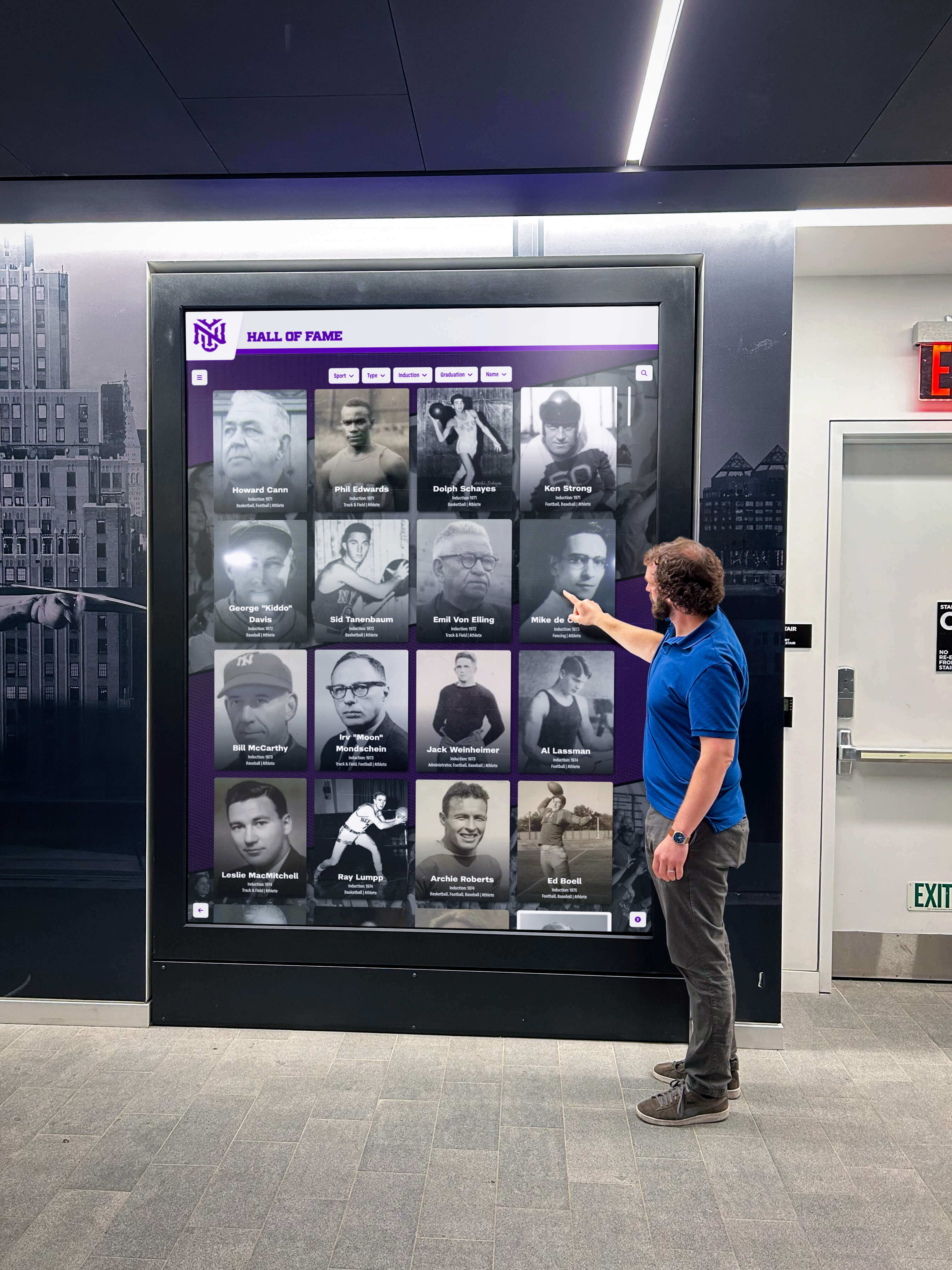
Lobby recognition displays are operated by visitors who have no knowledge of underlying technology — a phantom touch that navigates away from an athlete profile mid-reading reflects on the recognition program regardless of its electrical cause
EMI Test Acceptance Table: Pass, Conditional, and Reject Criteria
The following acceptance criteria are calibrated for school recognition displays serving non-technical visitors. A visitor interrupted by a phantom touch navigating the interface has no context for understanding the cause — the experience reflects on the recognition program, the institution, and the display technology equally.
| Test Condition | Pass (Acceptable) | Conditional Accept | Reject (Do Not Accept) |
|---|---|---|---|
| 15-minute idle phantom touch observation | Zero phantom touch navigations in 15 minutes under normal building operation | One phantom touch event in 15 minutes; event does not cause interface navigation (touch lands on non-interactive area) | Two or more phantom touch events in 15 minutes; any event causes interface navigation away from current screen |
| PA system activation test | No phantom touches or video artifacts during PA announcement | Minor video transient (single frame flicker) at PA start; no phantom touches; artifact not visible in normal recognition content | Phantom touch during PA announcement; sustained video banding or dropout during announcement |
| Lighting cycle test | No display behavior change when overhead lighting is cycled on or off | Single phantom touch event at light switch-on only; does not repeat during 30-second steady-state lighting operation | Multiple phantom touches or sustained video artifacts correlated with lighting state |
| Bell system test | No display response at bell activation | Single phantom touch at bell ring that does not navigate the interface | Bell ring causes phantom touch that navigates the interface or resets the display |
| HVAC motor start test | No display response at HVAC motor start | Brief touch unresponsiveness (under 2 seconds) at motor start; display resumes normal operation | Video dropout or extended touch unresponsiveness (over 2 seconds) at HVAC start |
| Ground continuity check | Under 1 ohm from display power plug ground pin to display chassis; outlet wiring correct | 1–5 ohm path resistance; outlet wiring correct | Over 5 ohm ground path; floating or missing ground; reversed polarity at outlet |
| Cable flex shielding test | No video artifact when cable is gently flexed near connectors | Transient artifact only at extreme flex angle unlikely in service position | Repeatable video artifact under gentle flex in the cable's normal service position |
Conditional accept guidance: A conditional acceptance for an EMI finding is only appropriate when the symptom occurs under a building system state that does not coincide with normal recognition display use hours. An overnight HVAC cycle start that produces a brief touch unresponsiveness at 2:00 AM is a different risk profile than the same symptom occurring at 3:00 PM when athletic banquet guests are in the lobby. Before accepting conditionally, confirm the building system schedule and verify the interference condition cannot occur during the display’s peak visitor hours.
Isolating EMI from Grounding Faults
Many symptoms that appear to be EMI coupling are actually grounding faults — conditions where the display, the media player, or the cable infrastructure does not share a common earth ground reference. Grounding faults and true EMI require different corrective actions, so distinguishing between them before ordering parts or calling an electrician saves significant time.
The three-way ground test. With the display powered on and the recognition interface active, measure AC voltage between the display chassis and a confirmed earth ground point (a known-good grounded outlet’s ground pin, or a building earth ground bar in the electrical panel). A reading of more than 0.5 VAC between the display chassis and earth ground indicates a floating or inadequate ground path. This condition, often called a “ground loop” or “floating chassis,” is the most common cause of systematic phantom touch behavior that appears independent of any specific building system.
Differential diagnosis: EMI versus grounding. True EMI interference from an external source — a ballast, a PA amplifier, a motor — is typically correlated: it appears when the source is active and disappears when the source is off. A grounding fault produces continuous phantom touch behavior that does not correlate with any specific building system cycle. If Step 1 of the EMI test (baseline with all systems at steady state) produces phantom touches before any deliberate interference activation, suspect a grounding fault before investigating external sources.
Common grounding fault causes in school installations. Three-to-two prong adapters on the display power plug eliminate the safety ground path. Extension cords with inadequate gauge or faulty ground conductors create high-resistance ground paths. Long daisy-chained power strips can accumulate enough ground resistance to leave the display effectively floating. In older school buildings, two-wire electrical circuits without a ground conductor in the wall are common — a recognition display powered from such an outlet requires a dedicated properly grounded circuit before EMI immunity testing is meaningful.
Academic recognition programs that invest in digital display technology expect that technology to be reliable from day one — a grounding fault that produces phantom touches on opening day is correctable, but it is a post-launch problem that could have been prevented with a pre-launch continuity check.
Athletic hall of fame programs that present decades of institutional sports history through interactive touchscreens depend on the display functioning correctly every time a coach, alumni, or community member steps up to the screen — interference-related reliability failures undermine the institutional credibility the recognition program was built to reinforce.
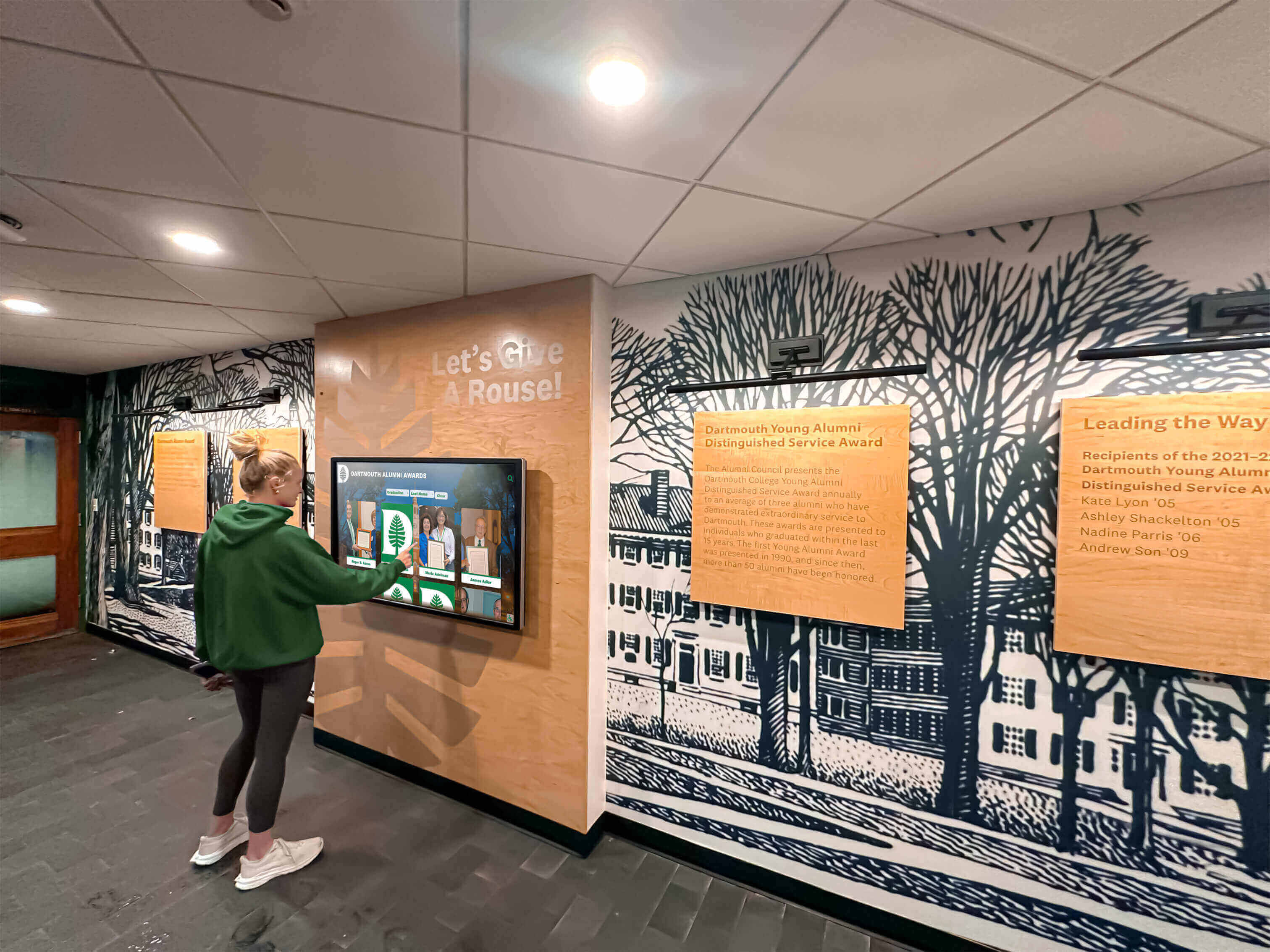
A student navigating an alumni recognition touchscreen should experience only the content — not phantom navigations, unexpected resets, or touch delays caused by electrical interference from the building environment
Corrective Actions for Common EMI Findings
Shielded Cable Replacement
When the cable flex test or the PA activation test reveals that the HDMI or DisplayPort cable is coupling interference, the first corrective action is replacing the cable with a premium shielded cable. Consumer-grade HDMI cables typically use a thin foil shield with 50–60% braid coverage. Commercial-grade HDMI cables use full foil-plus-braid shielding with a drain wire bonded to a properly grounded connector shell at both ends. In a school hallway with significant RF and conducted interference, the difference in immunity between these two cable grades is substantial.
When replacing the cable, also inspect the conduit path. An unshielded HDMI cable running through conduit that also carries HVAC power wiring may require separation into a dedicated conduit section. The National Electrical Code requires minimum separation between power and signal wiring in shared conduit depending on voltage level — a separation that, when maintained, also provides useful EMI isolation.
Power Conditioner or EMI Filter
When the HVAC start test or lighting test reveals conducted EMI on the display’s power supply input, a power conditioner with integrated EMI filtering on the line and neutral conductors is the most direct solution. These devices connect between the wall outlet and the display’s power cable and suppress high-frequency conducted noise while providing stable voltage. For recognition displays in schools — where utility power quality varies with building load throughout the day — a power conditioner also provides protection against voltage sags that can cause display restarts during peak afternoon operational periods.
Ferrite Core Installation
For radiated EMI coupling that cannot be resolved by cable replacement, clip-on ferrite cores installed on the HDMI, USB, and power cables near the display connectors provide additional high-frequency noise suppression. Ferrite cores are inexpensive, non-destructive, and reversible — they can be positioned, evaluated, and repositioned if needed. For the HDMI cable, a ferrite placed within six inches of each connector end addresses both the source-end and destination-end radiated pickup. For USB cables connecting the touch controller to the media player, a ferrite near the display-end connector reduces touch noise coupling that enters through the USB cable’s shield.
Branch Circuit Separation
When conducted EMI traces to shared electrical circuits — a display on the same branch as HVAC, PA equipment, or lighting dimmers — the long-term solution is a dedicated circuit for the recognition display. Electricians serving school facilities can typically run a dedicated 20-amp circuit from the electrical panel to a new outlet at the display location with minimal disruption. The investment in a dedicated circuit eliminates an entire category of conducted EMI paths and also ensures the display’s power quality is not affected by load fluctuations from other equipment on shared circuits.
Alumni wall and donor recognition programs installed in lobbies and entry corridors commonly share electrical infrastructure with building security, lighting control, and HVAC — requiring the same isolation practices that protect sensitive audio-visual equipment in performance spaces.
ACT recognition programs and academic achievement displays positioned in high-traffic corridors near electrical closets are particularly exposed to conducted EMI from network switching equipment and UPS systems in adjacent rooms — and benefit directly from the branch circuit separation practice described above.
Connecting the EMI Test to the Full Commissioning Sequence
The EMI interference test addresses electrical reliability. It should run as part of a complete commissioning sequence because other commissioning parameters interact with EMI immunity:
- Signal chain and resolution verification — confirm the display is receiving a clean, native-resolution signal before interpreting any touch behavior as interference-related. A display configured for the wrong resolution may generate touch registration errors that resemble interference.
- Cable continuity test — verify all conductor pairs in power, HDMI, USB, and Ethernet cables are intact. A broken shield conductor in a cable that passes visual inspection is a pre-existing EMI vulnerability.
- Ground continuity and outlet wiring check — complete the ground verification from Step 7 of this guide as a standalone check before any EMI source testing.
- EMI interference test — run the source-activation sequence and idle observation described in this guide.
- Phantom touch idle soak — leave the display running the recognition interface, unattended, for one hour minimum during normal school operating hours. Any phantom touch that navigates the interface will be visible in the recognition software’s session log if logging is enabled.
- Touch accuracy and edge linearity test — after EMI testing is complete, verify that intentional touches register accurately across the full panel surface, particularly at the edges where EMI-induced touch baseline drift most commonly occurs.
Athletic award program records maintained in digital recognition systems depend on consistent touchscreen operation to be accessible to the students, coaches, and alumni who visit the display — reliability testing before launch ensures those records are always reachable.
Museum and heritage recognition displays installed in public-facing environments require the same EMI commissioning discipline as school installations because they share the same vulnerability to mixed electrical environments — HVAC, lighting, and public address systems operating simultaneously with sensitive touch and video electronics.
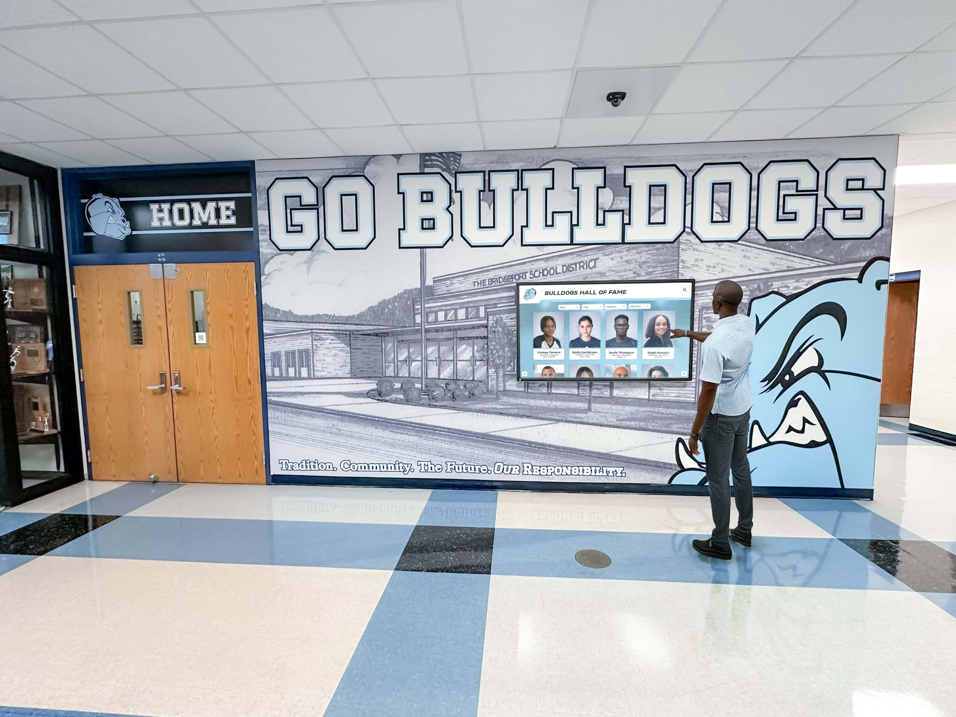
The full commissioning sequence — from cable continuity through EMI interference testing through touch accuracy — takes two to three hours and prevents the post-launch support calls that result from skipping any one of these steps
Pre-Event EMI Recheck
School recognition displays are most scrutinized at moments of peak community presence: athletic banquets, alumni weekends, championship celebrations, and formal ribbon-cutting events for new display installations. Running an abbreviated EMI check — the PA activation test, the lighting cycle test, and a five-minute idle phantom touch observation — one to three days before any scheduled high-visibility event confirms that the display’s interference immunity has not changed since initial commissioning.
Several conditions can degrade EMI immunity over time without anyone touching the display itself: a ballast replacement in an overhead fixture that introduced a higher-emission driver, a new PA amplifier installed in an adjacent equipment rack, a network switch added to the patch panel serving the display’s wall port, or seasonal HVAC system changes that brought a motor compressor into service closer to the display’s electrical circuit. None of these changes are announced to the IT coordinator responsible for the recognition display, and none of them are visible in the display’s content management logs.
Digital showcase boards for recognition programs that support high-stakes public presentations — an academic achievement display unveiled at a board of education meeting, a donor wall revealed at a capital campaign closing reception — require a pre-event EMI check as the final step before the cloth is pulled back and community members approach the screen for the first time.
Data integrity and reliability standards for recognition program content apply not only to the accuracy of the data itself but to the reliability of the display system presenting that data — a phantom touch that navigates away from a donor’s recognition panel mid-ceremony is a data presentation failure regardless of whether the underlying content is correct.
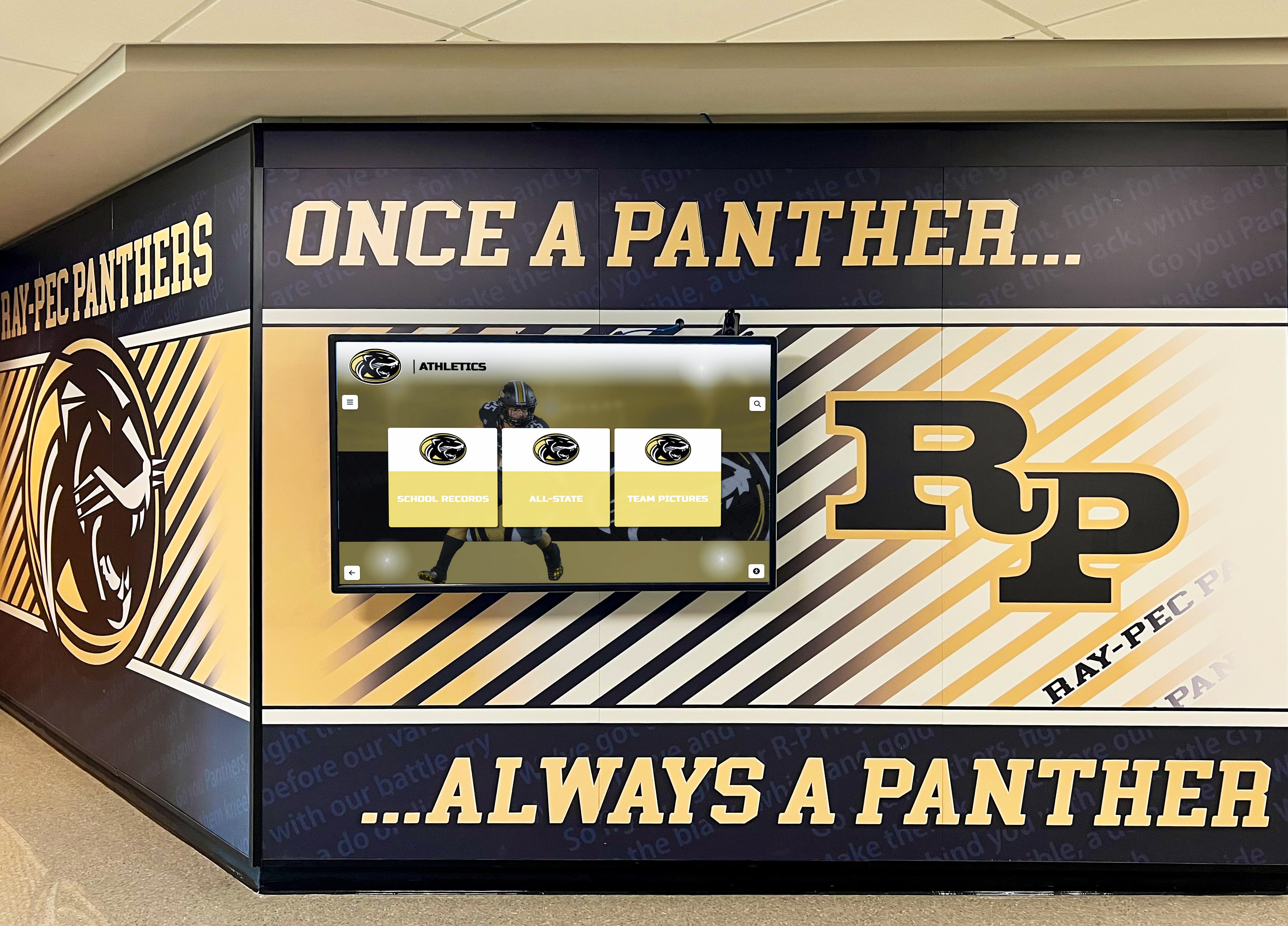
Pre-event EMI rechecks take 20 to 30 minutes and protect recognition programs from interference problems that developed since initial commissioning — a brief investment that prevents disruptions during the moments of highest community visibility
Frequently Asked Questions
What causes phantom touches on a school recognition touchscreen?
Phantom touches — touch events the display registers without anyone physically touching the screen — have two primary causes in school environments. The first is EMI coupling: electrical noise from fluorescent or LED ballasts, PA amplifiers, or HVAC motors radiates or conducts into the capacitive touch digitizer’s sensing circuit and registers as a touch event. The second is a grounding fault: the display chassis is not properly connected to earth ground, allowing the building’s ambient electrical field to appear as a large, slow-moving touch across the screen surface. Distinguishing between these two causes requires the baseline observation in Step 1 of this guide — a continuous phantom touch pattern that is present before any deliberate interference activation points to a grounding fault rather than a specific EMI source.
How far away from an EMI source does a recognition display need to be?
Radiated EMI field strength decreases with the square of the distance from the source. In practice, a three-foot separation from fluorescent ballast fixtures, PA amplifier chassis, and large motor enclosures is typically sufficient to reduce radiated coupling below the touch digitizer’s noise floor. The more important separation requirement is for cable routing: signal cables — HDMI, USB, and Ethernet — should not run parallel to power cables for more than two to three feet, regardless of absolute distance from the power cable, because parallel routing over longer distances accumulates inductively coupled noise even at physical separations of 12 inches.
Does EMI interference damage the recognition display hardware?
Ordinary EMI coupling in school environments does not damage display hardware. The interference affects the behavior of the touch digitizer and video signal chain — causing phantom touches and visual artifacts — without applying voltages or currents that exceed the hardware’s safe operating range. Conducted EMI on the power supply input is the exception: high-amplitude transients from motor starts or bell system transformers can stress power supply filter capacitors over time if the display is on a shared circuit with high-inrush equipment. A power conditioner with surge protection eliminates this stress path and protects the display’s power supply over its operational lifetime.
Can EMI interference explain why the recognition display worked in the vendor’s showroom but has problems on site?
Yes. Showroom and demonstration environments are typically purpose-built AV spaces with dedicated electrical circuits, shielded conduit infrastructure, and physical separation from HVAC, PA, and bell systems. A school building’s electrical environment is fundamentally different — multiple systems share electrical infrastructure in close physical proximity to the display’s installed location. A display that performs flawlessly in a controlled demonstration environment may exhibit phantom touch or video artifact problems on site without any change to the display hardware or software. The EMI test described in this guide is precisely the tool for identifying which aspect of the school environment is responsible and what corrective action will resolve it.
Should EMI testing be repeated after the touch screen software is updated?
Software updates to the recognition platform’s media player or the display’s internal firmware occasionally change the touch digitizer’s polling rate, noise filtering parameters, or USB communication timing in ways that affect EMI sensitivity. If a phantom touch problem appears after a software or firmware update on a display that was previously passing its EMI idle observation test, run the full source-activation sequence from this guide before assuming the update introduced a software bug. In some cases, the update exposed a pre-existing marginal EMI coupling that the previous software version’s different touch polling parameters happened to suppress.
A recognition display EMI interference test is a 60-to-90-minute procedure that maps electrical sources, activates building systems, and observes the display under realistic operating conditions before a school’s hall-of-fame, donor wall, or athletic record board touchscreen faces community visitors. Completing it during commissioning — and documenting findings with source correlation and zone locations — produces an interference-immunity baseline that supports both acceptance decisions and future troubleshooting. The cost of finding and correcting an EMI problem during installation is a cable replacement, a power conditioner, or an electrician visit. The cost of discovering it during a championship celebration ribbon-cutting or alumni banquet is a public-facing reliability failure that the recognition program carries long after the electrical issue is eventually resolved.
Ready to See a Recognition Display Done Right?
Rocket Alumni Solutions deploys interactive hall-of-fame, donor wall, and athletic record board touchscreens in schools nationwide — with structured commissioning processes that address EMI isolation, grounding verification, and display reliability from installation day forward.
Request a Demo