Intent: demonstrate — this recognition display edge linearity test guide walks school IT coordinators, athletic directors, facilities managers, and recognition-program administrators through confirming that every tap target on a hall-of-fame, athletic record board, or donor wall touchscreen registers accurately from corner to corner — including the sport filters, “Back” buttons, year selectors, and navigation controls positioned near every screen edge.
Touch linearity describes how accurately a touchscreen reports the position of a contact point relative to where the finger actually landed on the glass. A display with good linearity maps each touch to the correct screen coordinate. A display with poor edge linearity maps touches near the four screen boundaries to the wrong coordinates — often by enough that a visitor pressing a category button positioned close to the bezel must tap several centimeters away from the button’s visible location before it registers. That invisible offset undermines every part of the recognition experience: visitors abandon browsing, assume the display is broken, and miss content the school worked hard to present.
The quick answer: a recognition display edge linearity test places a grid of tap targets evenly across the full screen surface — including within 50 pixels of each edge — then taps each target once to confirm it registers inside its boundary. Any target requiring an off-center tap to register has a linearity error, and the pixel offset determines whether the panel passes, needs adjustment, or should be rejected before go-live.

Edge linearity errors are invisible to the eye but immediately felt by visitors — a sport filter or "Back" button that requires off-center tapping to register erodes confidence in the recognition display and discourages browsing
What Is Touch Linearity and Why Does It Matter at the Edges?
Touch linearity — sometimes called positional accuracy or touch position linearity — measures the distance between where a touch actually occurs on the glass and where the touchscreen controller reports it as occurring. A perfect panel reports every touch at exactly the pixel coordinate it occupies. Real commercial panels introduce small errors, and those errors are not uniform across the surface.
Edge linearity errors are larger than center errors on virtually every capacitive touchscreen for a physical reason: the electrode grid that senses touch is most accurate in the center of the panel, where the pattern repeats uniformly in all directions. Near the four edges, the electrode pattern terminates. The touch controller must interpolate position from a reduced set of surrounding electrodes, and the interpolation is less accurate. The result is that the outer 50–100 pixels of a display — exactly where navigation controls are commonly placed — are the zones most likely to produce registration errors that affect usability.
On a school recognition touchscreen, that matters for specific reasons. Day-to-day school storytelling through digital recognition displays depends on visitors navigating freely — filtering by sport, scrolling through inductee classes, tapping individual athlete profiles — without friction. When a navigation element placed near the screen edge requires an unintuitive tap offset to register, that friction appears as system unresponsiveness to the visitor, not as a hardware defect they can name. The recognition program suffers in silence.
Edge Linearity Error Reference Table
The table below provides an at-a-glance reference for the three screen zones, the types of errors that appear in each, and the corrective actions that apply.
| Screen Zone | Definition | Common Error Type | Primary Cause | First Corrective Action |
|---|---|---|---|---|
| Center | Middle 60% of panel area (away from edges) | Uniform small offset, typically ≤5 px | Factory calibration tolerance; slight glass flex | Run display's built-in touch calibration utility |
| Inner edge zone | 50–100 px inward from each panel edge | Moderate positional drift; off-axis bias toward center | Electrode pattern thinning near boundary; bezel pressure | Inspect and re-seat bezel mounting; update touch firmware |
| Outer edge zone | 0–50 px from each panel edge | Largest positional offset; touches pulled toward center | Edge electrode termination; insufficient edge compensation in firmware | Apply vendor edge-compensation calibration; contact manufacturer support |
| Corner clusters | 50×50 px area at each of the four screen corners | Bidirectional pull (both horizontal and vertical offset) | Combined horizontal and vertical edge effects compound at corners | Verify firmware supports corner correction; run four-corner calibration if available |
The Recognition Display Edge Linearity Test: Numbered Grid Method
The grid method is the most reliable field procedure for school IT teams and AV installation staff because it produces documented, repeatable results without requiring specialized calibration hardware. The only requirement is a full-screen tap target grid displayed on the panel under test.
What You Need
- A tap target grid image displayed at the display’s native resolution (typically 1920×1080 or 3840×2160). Free touchscreen test tools — including browser-based grid testers — allow you to display a 5×5, 7×7, or 9×9 grid of numbered tap zones on a connected display. A 7×7 grid (49 targets) provides adequate coverage of edge zones without making the test impractically long.
- A stylus or a fingertip — use a fingertip for consistency with how visitors will interact with the display.
- A printed or digital logging form with space to record each target’s pass/fail status.
- Two people: one tapping targets, one observing and logging results.
Step-by-Step Procedure
Display the grid at native resolution. Connect a laptop or media player to the recognition display via HDMI or DisplayPort and open the tap target grid at the display’s native panel resolution. Confirm the grid fills the full screen — no black bars — before beginning. This ensures the outer targets sit within the edge zone you are testing.
Warm up the display. Allow 10–15 minutes after power-on before testing. Capacitive touch sensor readings stabilize as the panel and glass reach operating temperature. Testing immediately after power-on may produce slightly elevated error readings that do not reflect steady-state performance.
Tap each target at its visual center. Starting from the top-left target, tap each numbered target once at the center of the visible target square. Do not adjust your tap position based on where you expect the registration to appear — the test measures where the display reports the touch relative to the visual center you tapped.
Record whether each tap registered inside the target boundary. The tap is a pass if the on-screen confirmation (a highlight, checkmark, or coordinate readout from the test tool) appears within the visible target boundary. It is a fail if the confirmation appears outside the boundary or fails to register after a single clean tap.
For failing targets, record the estimated pixel offset. If the tap confirmation appears consistently to the left, right, above, or below the tapped center, estimate the distance in pixels or millimeters. A test tool that displays the exact registered coordinate makes this step precise; visual estimation is adequate for field commissioning.
Pay particular attention to the grid’s outermost row and column on each side. These targets fall within the inner and outer edge zones and are the highest-risk targets for linearity failure. A 7×7 grid has 24 perimeter targets (the outer ring); all 24 should pass before the display is accepted.
Document results before the installation team leaves the site. A display with undocumented edge linearity failures that later affect visitor experience creates a much more difficult support interaction than one with a clear acceptance test record.
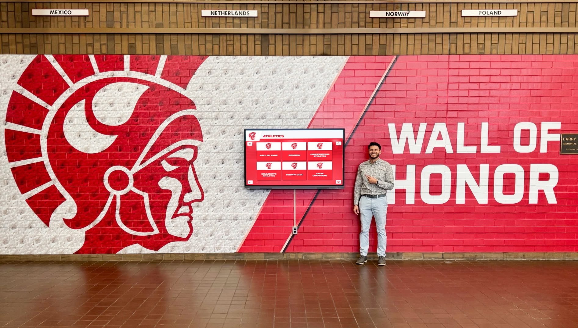
Recognition displays used by visitors of all ages must register taps accurately near every screen edge — a filter button near the bezel that requires off-center pressing to activate is effectively non-functional for most users
Error Tolerance Table for School Recognition Display Acceptance
The following tolerance table provides pass, marginal, and reject criteria by screen zone. These ranges reflect common commercial touchscreen vendor specifications and are appropriate for school recognition display installations where non-technical visitors are the primary users.
| Screen Zone | Pass (Acceptable) | Marginal (Conditional Accept) | Reject (Do Not Accept) |
|---|---|---|---|
| Center zone | ≤5 px offset in any direction | 6–10 px offset, consistent direction | >10 px offset, or inconsistent direction |
| Inner edge zone (50–100 px from edge) | ≤8 px offset | 9–15 px offset | >15 px offset |
| Outer edge zone (0–50 px from edge) | ≤12 px offset | 13–20 px offset | >20 px offset |
| Corner cluster (50×50 px at each corner) | ≤15 px combined offset | 16–25 px combined offset | >25 px combined offset |
Conditional accept guidance: A marginal result is appropriate to accept only when all navigation controls in the recognition software are positioned at least 80 pixels from any screen edge — meaning the marginal zone never overlaps a tap target in production. Before accepting a marginal result, confirm in the CMS layout that all interactive elements (sport filters, “Back” buttons, scroll indicators, year pickers) clear the affected zone.
Interpreting Results and Correcting Edge Linearity Failures
Failure in the Outer Edge Zone Only
This is the most common pattern and typically indicates a firmware or calibration issue rather than a defective panel. The outer 50 pixels exhibit elevated error because the touch controller’s edge compensation algorithm is not tuned for this installation’s display configuration.
First step: Run the display manufacturer’s built-in four-point or nine-point touch calibration utility. This utility — accessible through the display’s settings menu or the manufacturer’s companion application — re-maps reported touch coordinates to a reference grid and corrects uniform positional offsets.
Second step: If the calibration utility does not resolve the outer-edge error, check for a firmware update from the display manufacturer. Edge-zone compensation improvements are among the most common patches in commercial touchscreen firmware release notes. Apply any available firmware update and re-run the grid test.
Third step: If neither calibration nor firmware resolves the error, contact the display vendor’s technical support with the specific test results — zone affected, pixel offset measured, firmware version in use. A documented test result dramatically speeds the vendor support interaction compared with a general complaint that “the edges don’t work.”
Failure Uniform Across All Zones
A uniform error across the center and edge zones — where all targets are offset in the same direction by a consistent amount — typically indicates an offset calibration error rather than a linearity problem. The touch origin point is shifted, not distorted. Running the manufacturer’s calibration utility usually resolves this in a single step.
Failure Concentrated at One Edge
An error that appears only along one edge — the right side, for example — often indicates physical bezel pressure. If the mounting frame is pressing against one edge of the touchscreen glass, it distorts the capacitive sensor at that edge. The fix is mechanical: inspect the bezel mounting and verify that the frame is not applying uneven pressure to the glass perimeter. Loosen and re-seat the bezel if necessary, then re-test.
Interactive school recognition display programs that serve visitors across age ranges — elementary students, parents, alumni, and community members — are particularly sensitive to edge linearity failures because users who experience one unresponsive tap often abandon the display rather than trying again, directly reducing engagement with the athletic history and recognition content the school has invested in building.

Students, alumni, and community members interact with recognition displays at varying heights and reach angles — edge linearity testing accounts for the full visitor population, not just the installer's calibrated tap
Edge Zones That Matter Most for School Recognition Programs
The reason edge linearity is specifically consequential for school recognition displays — rather than for a display showing static content — is the placement of interactive navigation elements. Digital signage for schools in non-interactive mode places all critical information in the center of the screen. Interactive recognition platforms must place navigation elements where visitors will find them reliably, and convention places them near the edges.
The following navigation control types are most commonly placed in edge zones on hall-of-fame and athletic record board interfaces:
- Sport category filters — typically arranged as a horizontal row of buttons along the top or bottom edge, allowing visitors to filter inductees by sport (football, basketball, wrestling, swimming, etc.)
- Year or class selectors — year-picker menus or decade tabs often appear along the left or right edge as a vertical list
- Back and Home buttons — return navigation is commonly placed in the lower-left or lower-right corner, within the corner cluster zone where combined error is highest
- Scroll indicators — “More” or directional scroll arrows appear near bottom and side edges when content lists exceed a single screen
- Search or keyboard activation — search field activators may appear in the upper-right corner zone
Each of these elements benefits directly from a passing edge linearity test. Memorial recognition content — which includes faculty and coach tributes alongside athlete inductees — places particular importance on reliable navigation because visitors viewing sensitive content are less likely to retry a failed tap than visitors browsing casually.
Edge Linearity vs. Touch Sensitivity: Understanding the Difference
Edge linearity and touch sensitivity are related but distinct parameters. A display can have good sensitivity — registering every light touch — but poor linearity, meaning it registers the touch at the wrong coordinate. A display can have poor sensitivity — requiring firm pressure — but good linearity, meaning when a touch does register, it registers in the right place.
Both failures affect recognition display usability, but they feel different to the visitor. A sensitivity failure feels like the display is not responding. A linearity failure feels like the display is responding but in unexpected ways — tapping a button activates a different button, or a tap near the edge of the screen activates nothing at all because the registered coordinate falls outside any tap target.
The edge linearity test described here specifically isolates the positional accuracy component. For touch sensitivity testing — particularly palm rejection and detection threshold — the recognition display palm rejection test plan covers those parameters in detail.
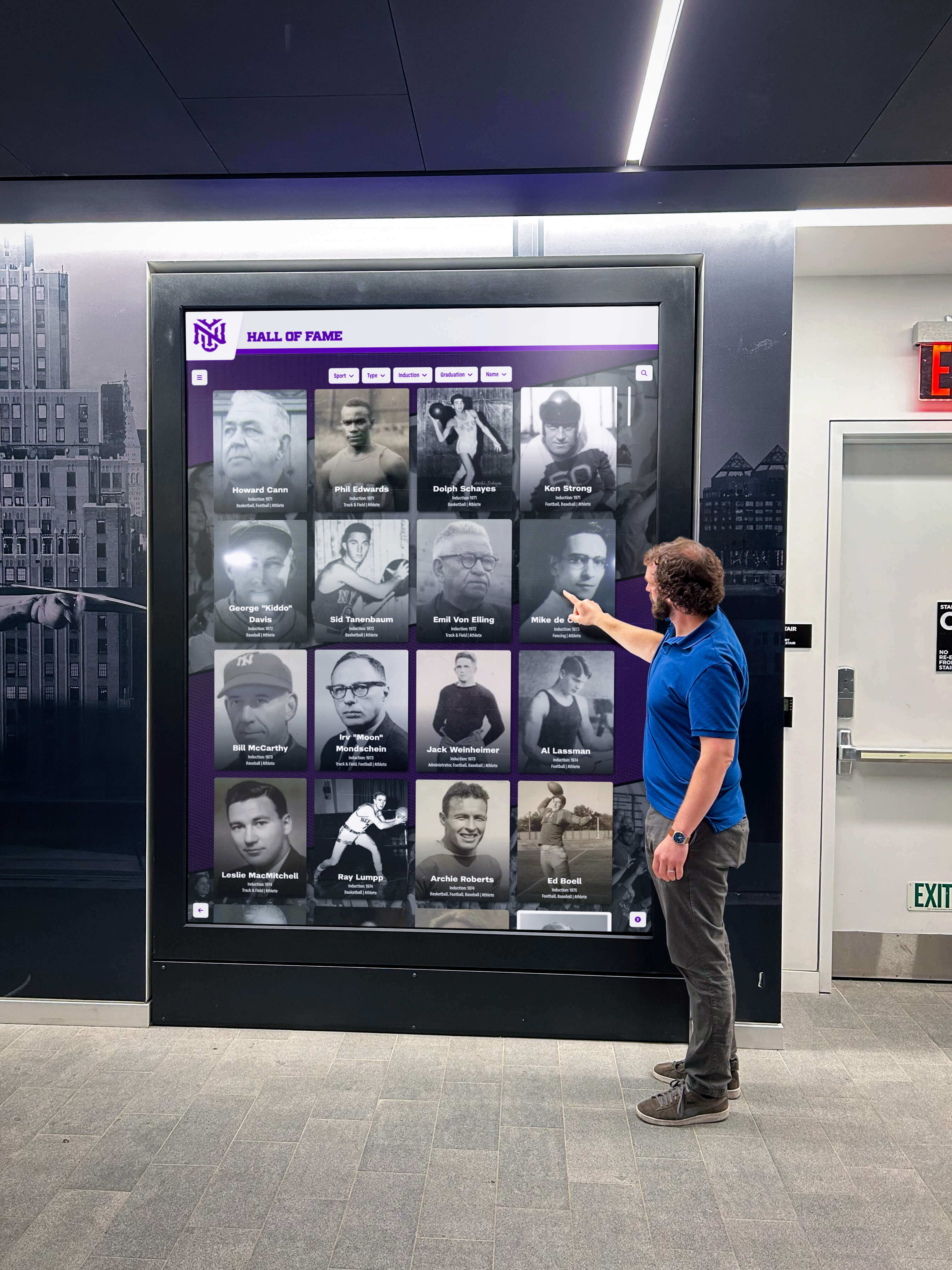
Understanding whether a touch failure is a sensitivity issue or a linearity issue determines the correct corrective action — the edge linearity test isolates positional accuracy specifically, independent of detection threshold
Coordination with the Broader Acceptance Process
The edge linearity test is one component of a full recognition display acceptance process. It should be run after geometry and signal-chain tests are complete — because a display receiving a non-native-resolution signal or exhibiting overscan will have incorrectly scaled touch coordinates regardless of the touch controller’s linearity.
The recommended sequence for school touchscreen commissioning:
- Signal chain and cable continuity — confirm correct signal delivery before any display tests
- Geometry and overscan — verify the image fills the panel without cropping or scaling
- Clipping and sharpness — confirm tonal and optical accuracy
- Edge linearity test — run the grid method described above
- Palm rejection test — verify incidental contact is filtered correctly
- Content management system access — confirm CMS can push content updates over the installed network
Athletic recognition platforms that offer unlimited screen support benefit particularly from a structured acceptance sequence because multi-display installations require consistent touch behavior across every panel — a linearity failure on one screen in a trophy corridor is immediately noticeable by visitors browsing from panel to panel.
All-conference award announcements and similar recognition content on digital displays depend on visitors being able to navigate to individual athlete profiles, class pages, and award detail screens reliably — which requires accurate touch registration at every position on the screen, including the edge zones where navigation controls live.
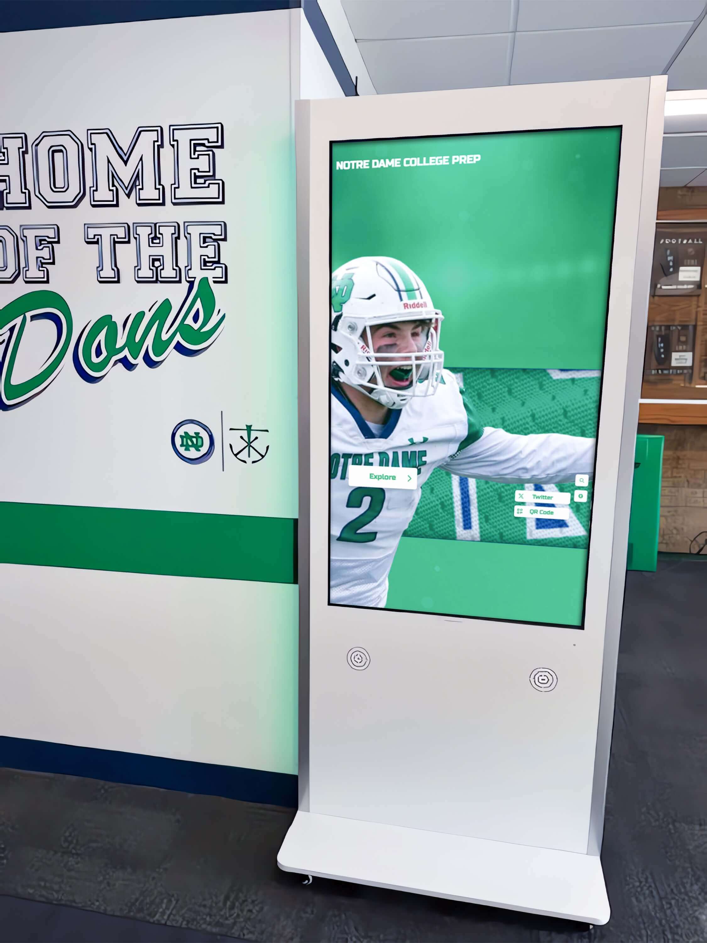
A recognition display kiosk in a school athletic hallway serves visitors across a wide age range — completing the full acceptance sequence, including edge linearity, before go-live ensures the display is reliable from the first day it is open to the public
Frequently Asked Questions
What is a recognition display edge linearity test?
A recognition display edge linearity test measures how accurately a touchscreen reports the position of taps near its four edges. The test displays a grid of tap targets evenly distributed across the full panel surface — including within 50 pixels of each edge — and records whether each target registers inside its boundary when tapped at its center. Targets that require off-center tapping to register have a linearity error; the size of the offset determines whether the display passes, receives a conditional acceptance, or should be rejected and corrected before the recognition program goes live.
Why are screen edges the critical zone for school recognition touchscreens?
Navigation controls on interactive recognition displays — sport filters, year selectors, “Back” buttons, scroll indicators — are typically positioned near screen edges by convention and design. If edge linearity is poor, these controls appear in the correct position visually but register touches from a nearby coordinate rather than the tapped location. Visitors experience this as the button failing to respond, or activating the wrong element, even when they tap precisely. Because most visitors do not retry a failed tap — they assume the display is faulty — edge linearity failures directly reduce engagement with recognition content.
How many targets should a recognition display edge linearity test grid include?
A 7×7 grid (49 targets) is adequate for most single-panel school recognition display installations. The outer ring of a 7×7 grid provides 24 perimeter targets that cover all four edge zones and all four corner clusters. For large-format displays (86 inches or larger), a 9×9 grid (81 targets) provides more granular coverage of the outer edge zone. The minimum acceptable grid for any acceptance test is 5×5 (25 targets), which provides 16 perimeter targets — sufficient to catch significant edge linearity failures but less granular for identifying the specific extent of marginal errors.
What causes corner cluster failures specifically?
Corner failures occur because the two adjacent edge effects compound: a target in the lower-right corner is affected by both the right-edge linearity error (which pulls the registration toward center horizontally) and the bottom-edge linearity error (which pulls registration toward center vertically). The result is a diagonal pull toward the center of the display that is larger than either individual edge error. Corner cluster errors that exceed the reject threshold — more than 25 pixels of combined offset — typically require either a firmware update with corner-specific correction or a four-corner calibration procedure from the display manufacturer.
Can we design around edge linearity failures by repositioning navigation controls?
Repositioning is a valid mitigation when edge linearity errors fall in the marginal range and a firmware correction is not immediately available. Any interactive element placed at least 80 pixels from the panel edge should clear the outer edge zone and land in the inner edge zone, where a marginal result may be conditionally acceptable. However, this mitigation works only if the recognition software’s layout is configurable — not all platforms allow repositioning of navigation controls — and it should be treated as a temporary measure while the underlying calibration or firmware issue is resolved, not a permanent workaround.
A recognition display edge linearity test is a 30-to-60-minute grid procedure that confirms sport filters, navigation buttons, year selectors, and scroll controls near every screen edge will register accurately for every visitor — from the elementary student who presses firmly in the center of a button to the alumni who lightly taps exactly where the label appears. Running the test before go-live, documenting the results, and correcting any failures while the installation team is still on site costs far less than investigating visitor complaints and scheduling a service call after the recognition program has launched.
Ready to See a Full-Featured Recognition Display in Action?
Rocket Alumni Solutions deploys interactive hall-of-fame, athletic record board, and donor wall touchscreens in schools nationwide — with structured commissioning processes that cover touch accuracy, edge linearity, and content management from day one.
Request a Demo