Intent: demonstrate — this checklist walks school facilities teams and IT coordinators through a recognition display cable continuity test so every power, network, HDMI, USB, and audio connection is verified fault-free before a touchscreen hall of fame, donor wall, or athletic record board goes live.
A cable continuity test confirms that each conductor in a run completes an unbroken circuit from source to destination. On a recognition display installation, hidden faults — a nick in an HDMI cable inside a conduit, a mis-crimped Ethernet connector, or a strained IEC power connection behind a wall mount — can pass visual inspection but fail under load, producing intermittent outages, signal dropouts, or a display that powers up in the installation bay and goes dark once mounted. Running a continuity check on every cable before the display is secured to the wall costs roughly 30–45 minutes and eliminates the most common source of post-installation service calls.
The quick answer: use a cable tester for Ethernet, HDMI, and USB cables and a multimeter set to continuity mode for AC power cables. Test each cable individually, confirm all conductors pass, and record results in the tracking table before mounting the display. Any cable that fails gets replaced before go-live — not after.
This checklist applies to wall-mounted and kiosk-style recognition displays connecting via HDMI, DisplayPort, or USB-C video; Ethernet for cloud-based content management; and AC power. It is hardware-neutral — the process is the same whether the installation is a 55-inch lobby screen, an 86-inch hockey rink touchscreen recognition display, or a freestanding kiosk in a trophy corridor.
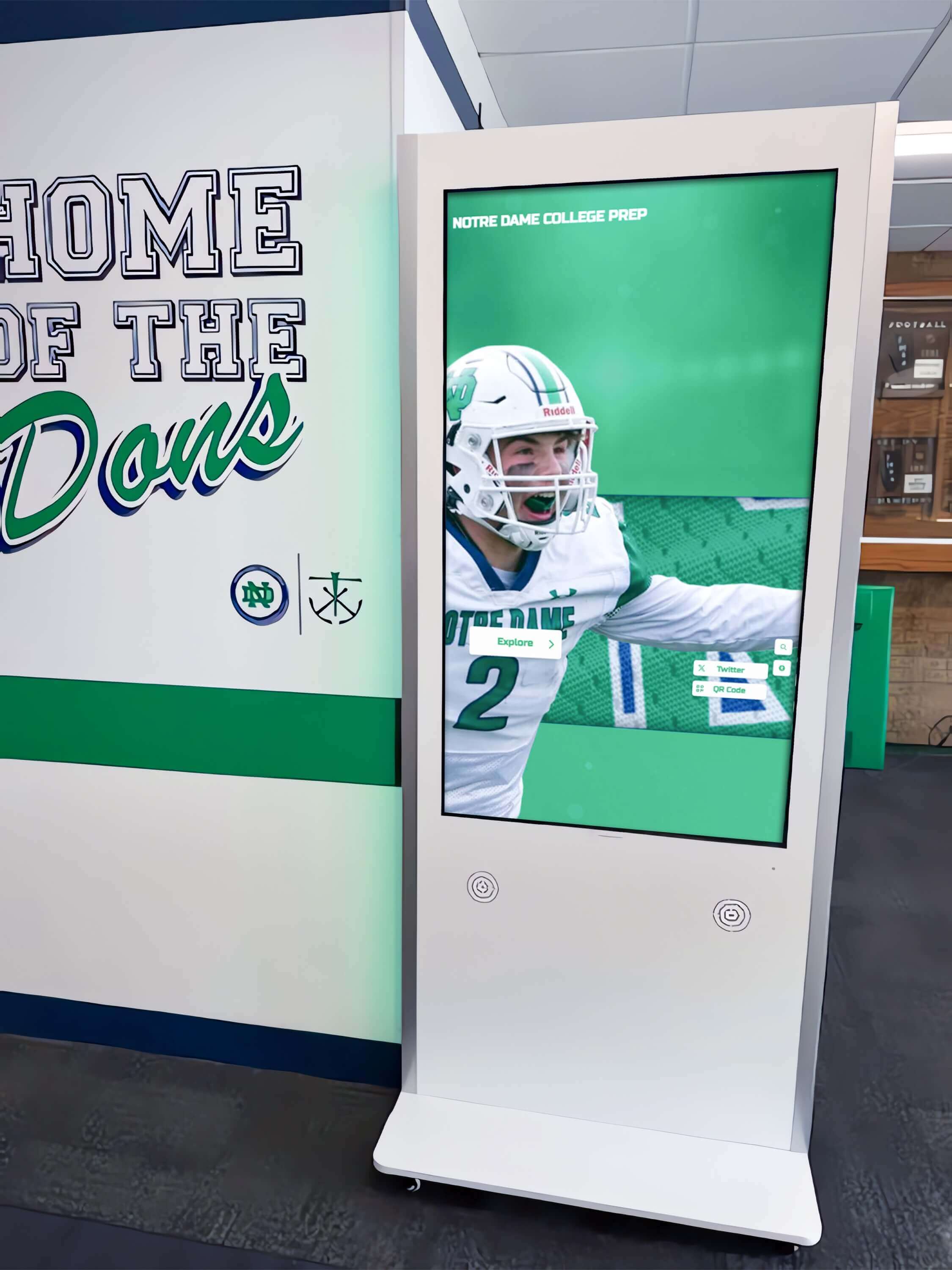
A 30-to-45-minute cable continuity check before wall mounting prevents the most common cause of recognition display outages on go-live day
Why Cable Continuity Matters for Recognition Displays
School recognition displays — hall-of-fame walls, athletic record boards, donor screens, and alumni archives — live in lobbies and corridors where a blank screen is immediately visible to students, families, and visitors. Unlike a back-office monitor, a recognition display with a cable fault produces a public-facing failure at the worst possible moment: a ribbon-cutting ceremony, a championship night, or a donor recognition event.
Three conditions make continuity testing especially important for school recognition installations:
Conduit and in-wall cable runs. Cables pulled through PVC conduit during construction or renovation pass through tight bends, staples, and junction boxes that can nick insulation or strain connectors. Once the conduit is filled and walls are closed, a hidden fault becomes expensive to access.
Extended cable lengths. Recognition displays in large gymnasiums, auditoriums, or athletics hallways commonly use HDMI or Ethernet runs of 25–50 feet. Longer runs amplify signal degradation from marginal conductor damage that would be invisible on a 6-foot cable.
Storage before installation. Cables purchased during a facility renovation may sit in storage for months before installation. Temperature cycling in equipment closets degrades connector crimps and accelerates insulation cracking at stress points near connectors.
Tools Required
| Tool | Use | Notes |
|---|---|---|
| Ethernet / network cable tester | Continuity and pinout verification for Cat5e, Cat6, Cat6a | Two-piece (remote/sender) models check both ends simultaneously |
| HDMI cable tester | All 19 HDMI conductors including hotplug and DDC lines | Look for models showing per-pin pass/fail |
| USB cable tester | Continuity for USB-A, USB-B, USB-C cables | Some combination testers include USB alongside HDMI |
| Multimeter (continuity mode) | AC power cords, ground verification | Audible beep mode is fastest for high-volume testing |
| Tone generator / probe (optional) | Tracing unlabeled cable runs in conduit | Useful during retrofit installations with existing infrastructure |
| Flashlight or inspection camera | Visual check of connectors before electrical testing | Bent pins and cracked insulation are often visible before testing begins |
A basic Ethernet tester costs under $30 at most electronics suppliers. A combined HDMI/USB/Ethernet cable tester consolidates signal cable checks into a single device and reduces setup time when multiple cable types are present in the same installation.
Pre-Test Visual Inspection
Complete a visual pass before connecting any cable to a tester. Visual defects found before testing are faster to resolve than tester failures that require re-tracing a cable back through conduit.
- Inspect both connectors on each cable for bent pins, corrosion, or cracked housing.
- Run your hand along the full cable length and note any hard kinks, flattened sections, or areas where the jacket is cut or abraded.
- Confirm that cables installed in conduit have strain-relief fittings at each end — connectors without strain relief commonly fail at the conduit entry point within the first year.
- For cables on reels or in storage packaging, verify there are no tight wraps indicating the cable was stored under tension.
Replace any cable with visible damage before testing. Visual defects that are not yet electrical faults will commonly become faults within the first 12 months of operation.
Recognition Display Cable Continuity Test Checklist
Step 1: AC Power Cable Continuity
Power cable faults are rare in new installations but more common in cables reused from previous equipment or stored in maintenance closets. A fault in the neutral or ground conductor may not prevent the display from powering on, but it creates a safety hazard and potential ground-loop interference visible as video noise on the recognition content.
Procedure:
- Set the multimeter to continuity mode (the diode symbol with audible beep, or the Ω symbol at its lowest range).
- Unplug the cable from all devices — never test continuity on a live circuit.
- Line conductor: touch probes to the line pin at each end. The meter should beep (continuity confirmed). Silence indicates an open fault.
- Neutral conductor: repeat for the neutral pin pair. Beep expected.
- Ground conductor: repeat for the ground pin pair. Beep expected.
- Cross-fault check: touch one probe to the line pin and the other to the neutral pin. No beep should occur. Repeat for line-to-ground and neutral-to-ground. Any beep here indicates a short that makes the cable unsafe to install.
- Record the result in the tracking table in Step 6.
Pass criteria: Continuity confirmed on all three conductors; no cross-faults between any pair.
Step 2: Ethernet / Network Cable Continuity and Pinout
Ethernet cables are the most likely cable type to arrive with a wiring fault when sourced from budget suppliers or self-terminated on-site. A standard Cat6 cable has eight conductors in four pairs. A fault on any single conductor interrupts network connectivity and prevents the recognition display’s cloud-based content management system from receiving updates.
Procedure:
- Attach the sender unit of a two-piece Ethernet tester to one cable end and the remote unit to the other.
- Power on the tester and observe the LED sequence for conductors 1 through 8.
- Confirm all eight LEDs illuminate in the correct sequence (straight-through: 1–1, 2–2, 3–3, 4–4, 5–5, 6–6, 7–7, 8–8). A crossed or missing LED indicates a fault or wiring error.
- For shielded Cat6a (STP), confirm the shield LED passes as well.
- Record the result.
Note on patch cords versus field-terminated runs. Factory patch cords from reputable vendors have a defect rate below 1% and usually pass immediately. Field-terminated runs — cables crimped on-site by installers — should be tested 100% because crimp errors are common. For recognition displays installed in renovated schools where cables were pulled and terminated years before the display project, treat all runs as field-terminated regardless of their original specification.
Pass criteria: All eight conductors pass; correct pinout sequence; no reversed or missing pairs.
Step 3: HDMI Cable Continuity
HDMI cables carry 19 conductors including three differential data pairs, a clock pair, CEC, DDC/EDID, and hotplug detect. A fault on any data pair produces signal dropout or handshake failure. A fault on the DDC/EDID pair causes the display to report incorrect capabilities, sometimes forcing a low-resolution fallback that makes recognition content — athlete portraits, award program detail, and graphics similar to content in school trophy and awards programs — appear blurry or incorrectly scaled.
Procedure:
- Connect the HDMI cable to the tester’s source and display connectors.
- Initiate a full-pin test and observe the per-pin result display or LED indicators.
- Confirm all 19 pins pass. Pay particular attention to:
- TMDS data pairs (pins 1–9): any fault produces visible image artifacts
- TMDS clock pair (pins 10–12): a fault prevents display synchronization
- Hotplug detect (pin 19): a fault prevents the display from signaling its presence to the source
- DDC/EDID (pins 15–16): a fault prevents the resolution handshake
- For cables longer than 15 feet (4.5 m), confirm the tester includes a signal-quality or attenuation check in addition to pin continuity. Long HDMI runs can pass per-pin continuity while having marginal signal integrity at 1080p or 4K operating frequencies.
- Record the result.
Pass criteria: All 19 pins pass; signal quality acceptable for the cable’s length.
Step 4: USB Cable Continuity
USB cables connect touchscreen overlay controllers, USB hubs, and peripheral devices to the recognition display’s host computer. A fault in the USB cable disables touch input — producing a display that shows content correctly but does not respond to taps, which is a high-visibility failure on an interactive hall-of-fame or award recognition screen.
Procedure:
- Connect the USB cable to the tester’s appropriate ports (USB-A, USB-B, USB-C, or Micro-USB, depending on cable type).
- Verify continuity on all conductors:
- USB 2.0: Power (VBUS), D−, D+, Ground — four conductors
- USB 3.x: Adds TX1+/TX1−, RX1+/RX1−, GND_DRAIN — nine conductors total
- USB-C Alt Mode (video): Use a tester that specifically covers Alt Mode pinout for cables carrying display signals
- Confirm no cross-fault between VBUS and Ground.
- Record the result.
Pass criteria: All conductors for the USB version in use pass; no VBUS-to-Ground short.
Step 5: Audio Cable Continuity (If Applicable)
Not all recognition displays use external audio, but installations featuring multimedia tribute videos, championship highlight reels, or accessible audio descriptions require a functioning audio path. Cable faults produce silence on one channel, ground-loop hum, or intermittent dropout.
Procedure:
- Set the multimeter to continuity mode.
- 3.5mm TRS: test tip-to-tip (left channel), ring-to-ring (right channel), and sleeve-to-sleeve (ground). Confirm no short between tip and ring.
- RCA: test center pin to center pin on each cable; shield to shield. Confirm no short between center pin and shield.
- Balanced XLR: test pin 1 (ground) to pin 1, pin 2 (hot/+) to pin 2, pin 3 (cold/−) to pin 3. Confirm no cross-faults between pins.
- Record the result.
Pass criteria: All signal conductors and ground pass; no shorts between channels or between signal and ground.
Step 6: Record Results and Make a Go / No-Go Decision
Document every cable tested before the display is mounted. This record becomes the installation baseline for future troubleshooting and a permanent component of the display’s documentation — as valuable to recognition program longevity as the school memorabilia and display preservation practices that guide long-term archival planning.
| Cable ID | Cable Type | Length | From | To | Test Result | Tester / Method | Tested By | Date | Action |
|---|---|---|---|---|---|---|---|---|---|
| PWR-LBY-01-01 | AC Power Cord | 6 ft | Display IEC inlet | Wall outlet J3 | Pass | Multimeter continuity | Cleared for installation | ||
| ETH-LBY-01-01 | Cat6 patch cord | 3 ft | Display ETH port | Wall jack J4 | Pass | Ethernet tester (8-pin) | Cleared for installation | ||
| VID-LBY-01-01 | HDMI 2.0 | 20 ft | Media player HDMI out | Display HDMI-1 input | Fail (pin 7 open) | HDMI cable tester | Replace cable before mounting | ||
| USB-LBY-01-01 | USB-A to USB-B | 4 ft | Display USB-A host port | Touch overlay controller | Pass | Cable tester USB function | Cleared for installation |
Go / No-Go rule: Every cable in the installation must show a passing result before the display is mounted. A single failing cable — particularly on power, network, or video — should be replaced, not deferred. Documenting a known fault as “will fix later” ensures it will not be fixed until it produces a public-facing failure.
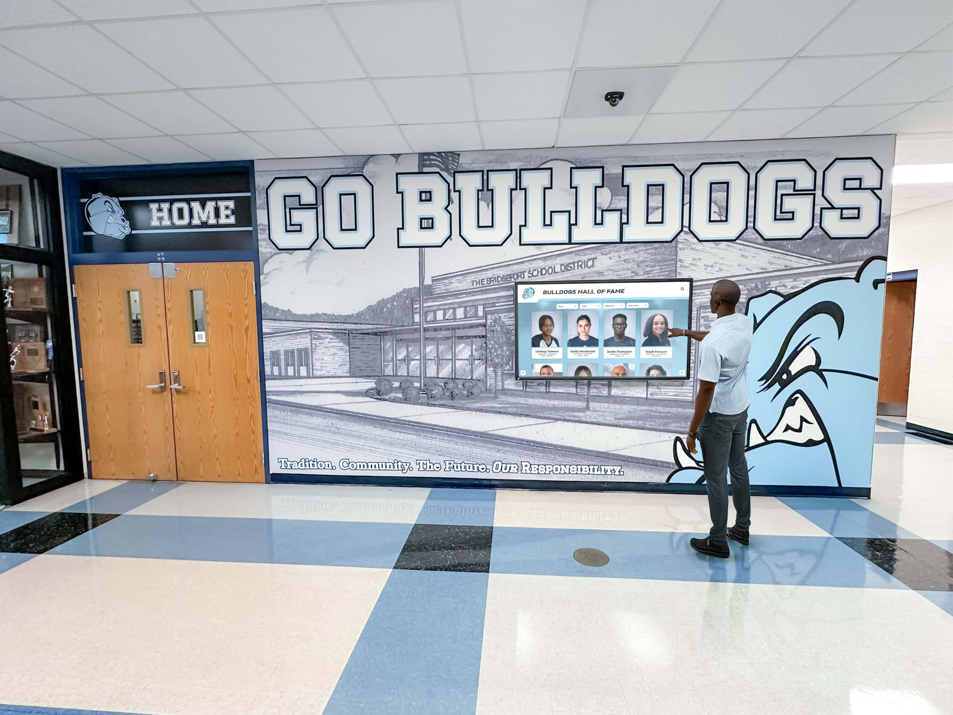
A complete cable test record allows any staff member to trace the source of a future outage without relying on the original installer's memory
Post-Test Installation Steps
After all cables pass continuity testing, complete these steps before declaring the installation finished:
- Apply cable labels using a consistent format (TYPE-LOCATION-DISPLAY-ID-PORT) so the continuity test record maps directly to each physical cable.
- Photograph the labeled cable bundle behind the display before the mount plate covers it.
- Store the completed test record in the school’s IT documentation system alongside the display’s serial number, network port assignment, and vendor contact details.
- Power up and perform a functional test — connect all cables, power on the display, and confirm network connectivity, video signal, and touch response before the display goes public.
- Note the test date and tester model in the installation record. This baseline matters when a cable fault appears during the warranty period — documented test results support a replacement claim and shorten the diagnostic conversation.
What to Do When a Cable Fails
A continuity test failure means the cable must be replaced before installation. The decision framework is straightforward:
| Failure Type | Action |
|---|---|
| Open conductor (no continuity on one conductor) | Replace cable; open conductors do not self-heal under use |
| Cross-fault / short between conductors | Replace immediately; shorts are a safety hazard on power cables |
| Partial HDMI failure (some pins fail) | Replace cable; partial faults produce intermittent failures that are harder to diagnose after mounting |
| Ethernet wrong-pair wiring | Re-terminate if field-crimped; replace if factory cable |
| USB VBUS-to-Ground short | Replace immediately; this fault can damage the connected host device |
Do not accept a “partially working” cable for a school recognition display. Athletic programs that track team recognition milestones and season records rely on consistent display uptime — a marginal cable that performs today will fail at the next high-stakes event.
Continuity Testing for Multi-Display Installations
Schools installing recognition display arrays — a common configuration for athletics hallways, donor corridors, or lobby triptychs that might feature records for basketball programs and past championship teams alongside other sports — should test all cables before any display is mounted, not one display at a time.
The reason: cable runs from a central media source to multiple displays often share conduit for part of their length. A fault discovered on display 3 may require pulling all cables out of the shared conduit segment to replace the affected run. Testing all cables before any installation starts — and having replacement stock on-site — eliminates the scenario where a partially completed installation must be dismantled to access a cable fault discovered late.
For multi-display setups, extend the tracking table with a display identifier column and record a separate go/no-go sign-off for each display before beginning any mounting work.
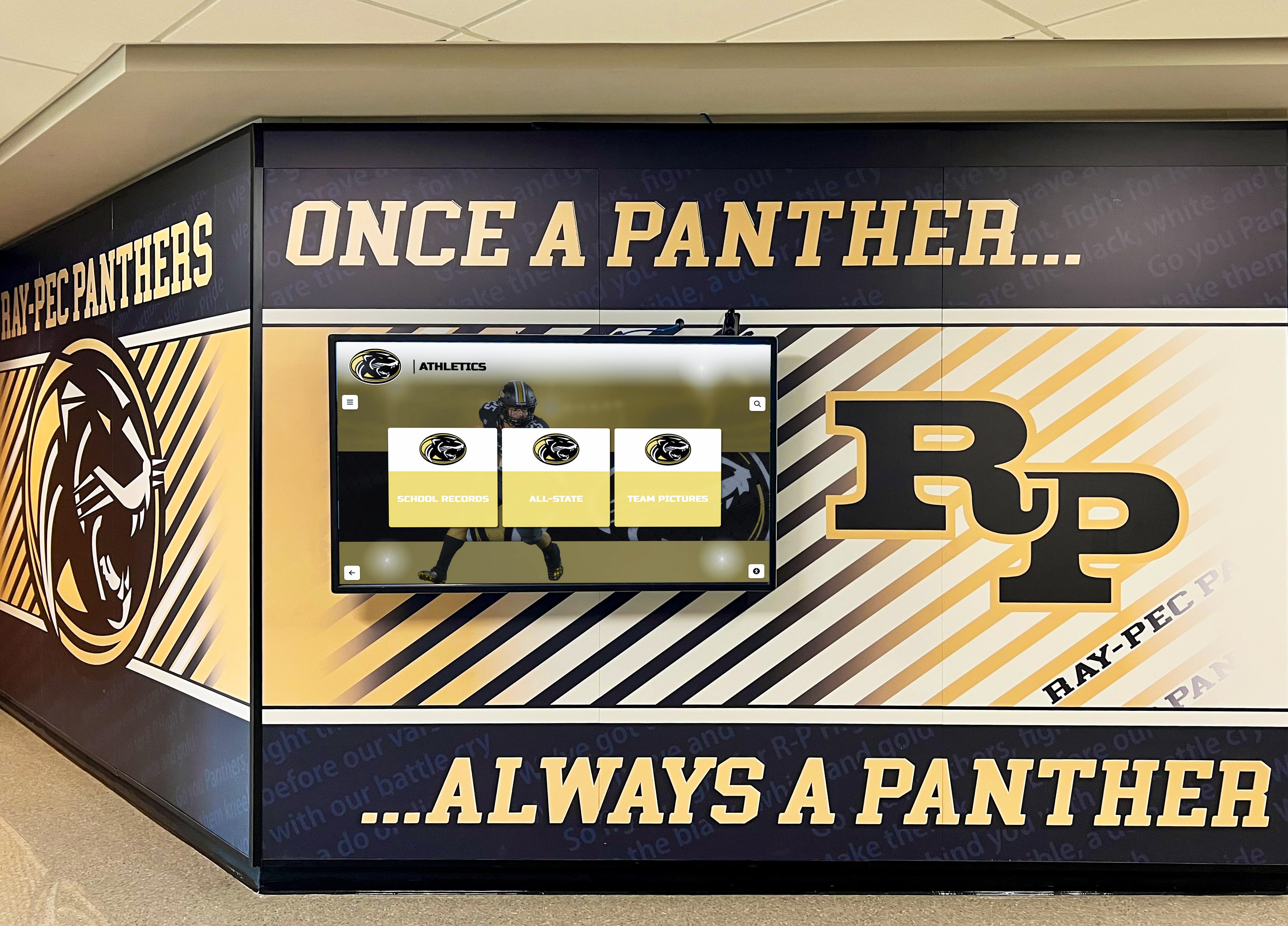
Multi-display hallway installations require a completed continuity test record for each display before any mounting begins
Frequently Asked Questions
How long does a recognition display cable continuity test take?
A typical five-cable installation (power, Ethernet, HDMI, USB, audio) takes 30–45 minutes including the visual inspection, individual cable tests, and documentation. Each additional cable adds roughly five minutes. Multi-display installations scale proportionally — testing all cables for a three-display hallway typically runs 90–120 minutes.
Do we need to test factory cables or only field-terminated ones?
Both should be tested. Factory cables have a low defect rate but are not zero-defect, and cables that have been in storage, handled roughly, or briefly used in a prior installation may have connector damage not visible without testing. The time cost of testing a factory cable is under two minutes; the cost of discovering a fault after the display is mounted and walls are closed is substantially higher.
Can we use a tone generator instead of a cable tester?
A tone generator and probe can confirm that a cable run is continuous from one point to another, but it does not test individual conductors within a multi-conductor cable or identify cross-faults. Use a dedicated cable tester for any cable type where per-conductor results matter — Ethernet, HDMI, and USB. Tone generators are useful for locating and identifying unlabeled cables before the formal test sequence begins.
Should we repeat the continuity test after the display is mounted?
A post-mounting re-test is optional but recommended for HDMI cables in kiosk enclosures or wall cavities where the cable is routed around tight bends during installation. If the routing process involved pulling, bending, or securing the cable with ties after the initial test, a five-minute re-test on the HDMI run confirms the routing process did not introduce a new fault.
What is the difference between a continuity test and a signal test?
A continuity test confirms that each conductor forms an unbroken circuit from one end of the cable to the other. A signal test (certification testing for Ethernet, or a handshake test for HDMI) confirms that the cable can carry the intended signal at the required speed and quality. For most school recognition display installations, a continuity test is sufficient. HDMI runs longer than 25 feet and Ethernet runs in environments with high electromagnetic interference benefit from a signal test as well, to confirm adequate quality at operating frequency.
Our display vendor handles installation — do we still need to run continuity tests?
If a vendor provides a managed installation service that includes cable testing and documentation as a deliverable, you may not need to run independent tests. Confirm what the service covers: does the vendor test each cable individually and provide results, or do they install and power up as a functional check only? A successful power-up confirms the display works with those cables on installation day; it does not document each cable’s fault status for future reference. Schools that own the display long-term benefit from having the cable test record regardless of who performed the tests.
How does this checklist relate to broader installation documentation?
A cable continuity test record is one component of the full installation documentation package alongside VESA mount inspection records, cable labeling maps, network port assignments, and software configuration notes. Schools building recognition programs that span decades — hall of fame archives, donor walls, and athletic record boards — need infrastructure documentation that outlasts individual staff members. A verified cable record stored at installation gives any future IT coordinator a reliable baseline when the display requires service years after the original team has moved on.
A recognition display cable continuity test adds 30–45 minutes to a school installation and permanently reduces the risk of post-installation cable faults. Test every cable individually, record every result, and make a documented go/no-go decision before mounting. Replace any failing cable before installation — the cost of a replacement cable is always less than the cost of dismounting a wall-hung recognition display to access the cable behind it.
Looking for a recognition display partner that owns the installation quality from cable to content? Rocket Alumni Solutions manages the full installation process — including hardware commissioning, cable verification, and content configuration — so your school’s hall of fame, athletic record board, or donor wall is ready to run without a last-minute troubleshooting session. Request a demo to learn how their managed approach compares to self-managed display installations.